 EN
EN 中文
中文 ES
ES RU
RU FR
FR PT
PT AR
AR DE
DESolving False Echoes in Tall, Narrow Silos with 80 GHz Radar

Tall, narrow silos are some of the hardest vessels to instrument reliably, and a silo false echo radar problem is usually the root cause when a level reading drifts, sticks, or jumps without explanation. When a silo measures only a few meters across but extends twenty, forty, or more meters in height, every ladder rung, inlet pipe, baffle, and weld seam sits close to the measurement path. Each of those features can reflect microwave energy back to the sensor and masquerade as product. The result is a reading that no longer tracks the real material surface. This article explains where false echoes come from, why a narrow-beam 80 GHz radar reduces them, and how careful aiming, mounting, and false echo mapping turn a difficult vessel into a stable measurement point.
What a False Echo Actually Is
A non-contact radar level transmitter works by emitting a microwave signal toward the product surface and timing the energy that returns. In a clean vessel, the strongest return comes from the material itself, and the electronics convert that travel time into a distance and then a level value.
A false echo is any reflection that does not come from the true product surface. Inside a real silo, the radar signal does not travel in a perfectly clean cone. Some of it strikes internal structures, the wall, or residual buildup, and bounces back early. The transmitter sees several returns at different distances and must decide which one is the genuine surface. When a structural reflection is stronger than the product echo, or arrives at a distance the firmware cannot rule out, the device can lock onto the wrong target.
In tall, narrow silos this is especially common because the measurement path is long and the walls are close. The longer the distance, the weaker the true echo becomes by the time it returns, while fixed internal features keep producing the same strong, constant reflections regardless of fill level.
Why Tall, Narrow Geometry Breeds Interference
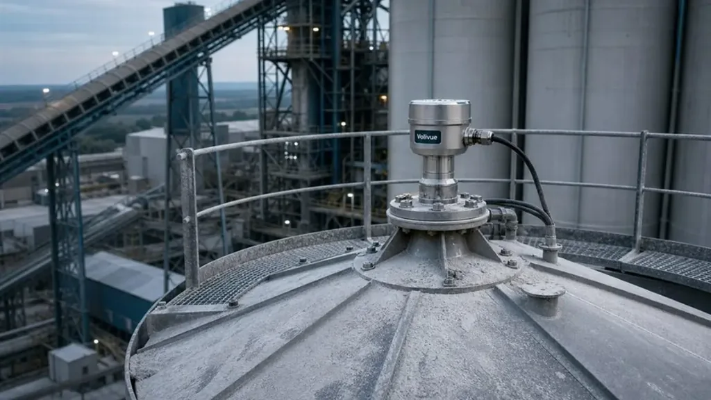
Several characteristics of slim, high silos work together to create false echoes:
- Close sidewalls. A narrow diameter means the beam edge is never far from the wall. Any beam spread that touches the wall produces a reflection that competes with the product echo.
- Ladders and cages. Internal access ladders, cage rails, and their support brackets are metallic, vertical, and persistent. They return strong, stable echoes at fixed distances.
- Inlet and fill pipes. A central or angled fill pipe sits directly in the most common mounting zone and reflects energy back almost continuously.
- Baffles, beams, and stiffeners. Reinforcing rings, anti-buckling stiffeners, and structural cross-members are added to tall silos precisely because the geometry demands extra rigidity, and each one is a potential reflector.
- Long measuring range. As level drops in a deep silo, the product surface can be far from the sensor. A weaker, more distant true echo is easier for a strong nearby structural echo to overwhelm.
Buildup and material caking on the wall add a further layer of difficulty, because a coated surface can scatter the beam or generate slowly changing echoes that the transmitter has to separate from real level movement.
How 80 GHz Narrow-Beam Radar Reduces False Echoes
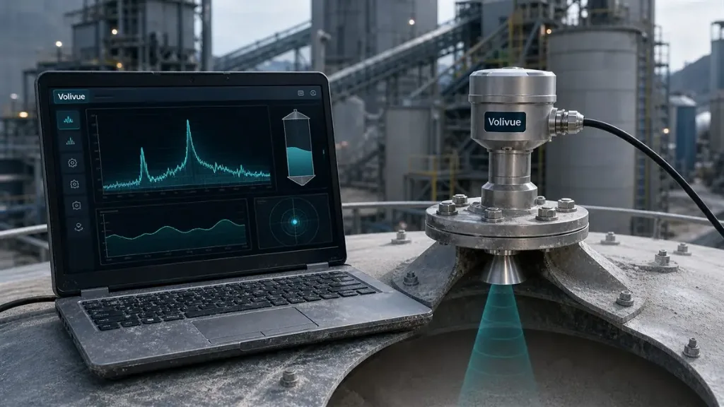
The most effective hardware-level answer to this problem is a higher operating frequency. The Volivue 80 GHz Radar Level System uses 80 GHz FMCW (frequency-modulated continuous wave) technology with a narrow lens-antenna beam of approximately three degrees. That tight beam is the single most important property for tall, narrow vessels.
A narrow beam concentrates the radar energy into a slender column that travels down the silo with far less spread than a wide, lower-frequency beam. Because the cone stays tight, it is much easier to point the energy between the ladder and the wall, past the inlet pipe, and onto open product surface. Less of the signal grazes internal structures, so fewer false echoes are generated in the first place. This is fundamentally easier to commission than trying to suppress dozens of strong reflections after the fact.
The 80 GHz approach also concentrates more return energy on the actual surface, which improves the strength and clarity of the true echo relative to background reflections. Combined with the non-contact design, the sensor never touches the product, so it is unaffected by the abrasion, bridging, and load that defeat mechanical and contact devices in tall silos.
Beyond the beam, the system offers practical signal flexibility for plant integration. Measuring range is typically 0.1 to 120 m and accuracy is typically in the range of plus or minus 2 mm to plus or minus 3 percent, both model dependent, which covers the working depth of most tall silos. Outputs include 4 to 20 mA, HART, RS485 Modbus, and PROFIBUS PA, and the enclosure is rated IP67 or IP68. Hazardous-area variants are available depending on the model where dust or combustible product classification requires it. Selecting the correct variant for the silo contents and zone is part of the planning conversation rather than an afterthought.
Beam Alignment and Mounting Position
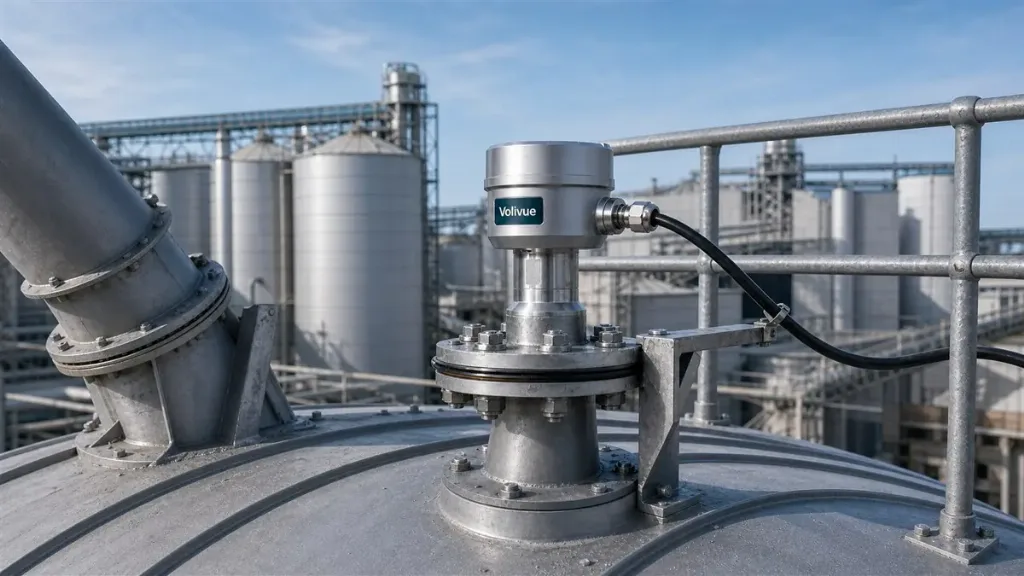
Even the narrowest beam has to be aimed correctly. In a tall, narrow silo, mounting position and alignment do more for measurement quality than almost any firmware setting.
- Keep the beam clear of internal structures. Position the sensor so the projected beam path runs through open space, not along the ladder, the inlet pipe, or a row of stiffeners. A short offset across the silo roof can move the beam path from “grazing the ladder” to “completely clear.”
- Respect a minimum distance from the wall. Mounting too close to the sidewall guarantees wall reflections. Place the device far enough inboard that the beam edge does not clip the wall over the full measuring range.
- Aim toward the product, not the structure. Where the silo roof allows, orient the antenna so the beam centers on the deepest reachable surface. For very tall silos, even a small angular error projects into a large lateral offset at the bottom, so deliberate aiming matters.
- Avoid the active fill stream. Do not place the sensor directly over the incoming material flow, where falling product and dust clouds create transient, unstable echoes.
- Use the antenna and process connection suited to the nozzle. A clean, correctly sized nozzle that does not protrude into the beam keeps near-zone reflections out of the signal.
Good mechanical placement reduces the number of false echoes the electronics ever have to deal with, which makes the software steps that follow far more robust.
False Echo Mapping and Suppression
After the sensor is mounted and aimed, false echo mapping is the commissioning step that teaches the transmitter to ignore the structural reflections that remain. This feature, often called false echo suppression or a stored echo curve, records the silo’s fixed reflection signature so the device can subtract it from live measurements.
The principle is straightforward. With the silo emptied as far as practical, or with the product surface known to be below a defined point, the transmitter scans the vessel and captures the echoes coming from ladders, pipes, baffles, and the wall. Because these structures do not move, their reflections appear at the same distances every time. The device stores this map and treats those fixed returns as background, so they no longer compete with the genuine product echo as the level rises and falls.
A few practices keep mapping effective:
- Map against a known low level. The lower the product when mapping, the more of the silo’s internal structure the device can characterize and suppress.
- Do not map over real product. If a strong genuine echo is recorded as a false echo, the transmitter may later ignore the real surface at that distance. Mapping should capture structure, not material.
- Re-map after mechanical changes. Adding a new baffle, ladder section, or fill pipe changes the echo signature, so the stored map should be refreshed.
- Combine mapping with good placement. Suppression is most reliable when there are only a handful of fixed echoes to manage, which is exactly the situation a narrow 80 GHz beam and a clean mounting position create.
Commissioning and Verification Checklist
A disciplined commissioning sequence turns these principles into a stable, trustworthy loop. The following steps consolidate the field practice for tall, narrow silos:
- Confirm geometry and obstructions. Document silo height, diameter, and the location of every ladder, pipe, baffle, and stiffener before choosing a mounting point.
- Set the empty and full reference. Enter the correct empty distance (sensor face to silo bottom) and the full point, so the span matches the real working range.
- Verify beam clearance. Check that the aimed beam path does not intersect known structures over the full range.
- Run false echo mapping at a known low level. Capture and store the fixed reflection signature, then confirm the device tracks the real surface as material is added.
- Validate against a reference reading. Compare the radar value with a manual dip, load-cell estimate, or known fill quantity to confirm the device is following product, not structure.
- Test through a fill and empty cycle. Watch the reading through real material movement, including dust-heavy filling, to confirm there are no jumps to fixed-distance false echoes.
- Record the configuration. Save the parameters, echo map, and reference checks so the setup can be reproduced or audited later.
When these steps are followed with a narrow-beam non-contact radar, a tall, narrow silo that once produced erratic readings becomes a dependable measurement point that supports inventory accuracy, overfill protection, and process control.
False echoes are not an unavoidable cost of difficult silo geometry. They are a solvable combination of physics and setup: a tight 80 GHz beam to generate fewer interfering reflections, deliberate mounting and alignment to keep the path clear, and false echo mapping to suppress whatever structure remains. To review the full specification and signal options of the Volivue 80 GHz Radar Level System, or to discuss a specific tall-silo application with our engineering team, request an application review.
Related Reading
Explore more field-engineering guides and measurement fundamentals in our Technical Insights library.