 EN
EN 中文
中文 ES
ES RU
RU FR
FR PT
PT AR
AR DE
DERadar Level SCADA Integration: 4–20 mA/HART, Modbus, and Relay Paths to PLC and DCS
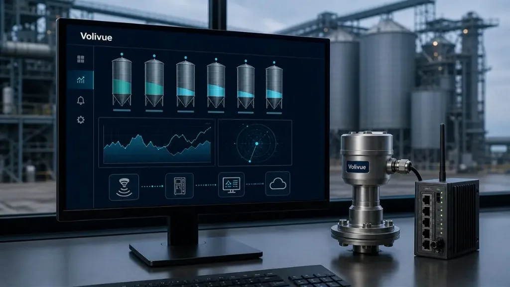
Radar level SCADA integration is the engineering work of getting a tank level measurement out of the transmitter and into the system that has to act on it — a PLC, a DCS, or a SCADA server. The sensing technology is settled: an FMCW non-contact radar measures distance to the liquid surface and derives level without touching the medium. The open question on every project is the path. The same level value can travel as a 4–20 mA current loop with HART riding on top, as a digital multivariable read over RS485 Modbus, or as a relay contact wired straight into an alarm or interlock. Those three paths differ in latency, data richness, wiring effort, and how cleanly they close the loop with your control and asset-management systems.
This article maps the three output paths offered by a Volivue radar liquid level transmitter onto the control architecture that consumes them: where each path fits, how loop power and wiring are arranged, what HART adds for diagnostics and asset management, and how relay outputs slot into alarm and interlock logic. The aim is a transmitter that reports the same trusted level to the control loop, the historian, and the maintenance team without forcing any one of them to read another’s system.
The three output paths and where each fits
The transmitter exposes four electrical interfaces — 4–20 mA, HART, RS485 Modbus, and a relay output — but in practice they resolve into three integration paths, because HART is layered on the same wires as the 4–20 mA loop.
- 4–20 mA + HART carries the primary level as an analog current and, optionally, digital data superimposed on the loop. It is the conservative default in process plants and the one most DCS and PLC analog input cards expect.
- RS485 Modbus puts the transmitter on a serial bus speaking Modbus RTU, where a SCADA server or PLC can poll level plus secondary variables and device status from many transmitters over one twisted pair.
- Relay output provides a dry contact that switches at a configured level threshold, feeding a high/low alarm or an interlock directly without any protocol stack between the transmitter and the action.
These are not mutually exclusive. A common arrangement uses the 4–20 mA loop for control, HART for commissioning and diagnostics, and the relay as an independent high-level cutout that does not depend on the control system being healthy. The decision is driven by who consumes the data and how fast they must act on it.
Path A: 4–20 mA with HART into PLC or DCS

The analog path maps the configured measuring span — anywhere within a typical 0.1–30 m range depending on model — onto a 4–20 mA current, wired into an analog input channel on the PLC or DCS. It remains the default in continuous process control.
Where it fits. Storage tanks, day tanks, buffer vessels, and any application where level participates in closed-loop control, batching, or interlocks and must be sampled deterministically. If a level value drives a control valve or a pump VFD, the analog loop into the controller is the right answer.
Strengths. The loop is effectively real time, needs no protocol stack, and current signaling tolerates long cable runs and electrically noisy plant environments. Two-wire loop-powered transmitters draw their operating current from the same pair that carries the signal, so a single twisted pair handles both power and measurement back to the input card.
Trade-offs. The analog value carries one variable — level — and nothing else. Every transmitter needs its own input channel and cable run, and the PLC scaling must match the transmitter span exactly, or drift becomes a silent offset. The diagnostics that would catch that drift live in HART, which is why the two are almost always specified together.
HART on the same loop. HART superimposes a low-level digital signal on the 4–20 mA loop, so the same two wires that carry the primary level value also carry digital data without disturbing the analog reading the controller sees. Beyond the primary level, HART exposes secondary variables, configuration, and diagnostic status — signal quality, echo confidence, and fault flags that an analog current alone cannot express. A handheld communicator or an asset-management system reads these over the loop.
Asset management and commissioning. HART lets a technician set the empty and full reference points, adjust damping, and confirm the echo is locking onto the liquid surface rather than an internal obstruction — without breaking the loop or climbing the tank repeatedly. In a plant running an asset-management platform, the same diagnostics stream back so a degrading signal shows up as a trend before it becomes a failed measurement. HART does not change real-time control behavior — the analog value still drives the loop — but it removes the blindness of a bare current signal, so specify it wherever you want the analog path’s determinism plus the ability to diagnose the transmitter without a site visit.
Path B: RS485 Modbus into SCADA

The Modbus path puts the transmitter on an RS485 serial bus speaking Modbus RTU, polled by a SCADA server, PLC, or local HMI. One twisted pair can address multiple transmitters.
Where it fits. Sites standardized on SCADA, installations with several tanks in one area, and operations that want trend logging, multivariable data, and device status without a separate analog channel per vessel — where the consumer is operations and inventory visibility rather than a hard control loop.
Strengths. A single bus reads many transmitters, cutting wiring versus one analog channel per tank. Registers can expose more than a single number — level, distance, and device status — so SCADA gets richer context than an analog loop. Polling, historian logging, setpoints, and alarm thresholds all live in tools the controls team already operates.
Trade-offs. Polling latency depends on bus speed, device count, and poll interval — fast enough for trending and inventory, but not for sub-second interlocks. RS485 wiring needs discipline: proper termination and biasing, and separation from VFD and motor cabling. Register maps, byte order, and scaling factors must match exactly between transmitter and master, or the values look plausible while being wrong. Pair Modbus with a relay or analog path wherever a fast interlock is required.
Path C: relay output for alarm and interlock

The relay output is a dry contact that changes state when level crosses a configured threshold. It is the simplest path and, deliberately, the most independent.
Where it fits. High-level overfill protection, low-level dry-run or pump-protection cutouts, and any interlock that should act even if the control system or communication bus is down. Because the contact switches in the transmitter itself, the action does not wait on a PLC scan or a Modbus poll.
How it integrates. Wire the contact into a PLC digital input for annunciation and logging, or directly into a control circuit — a pump starter, a fill valve solenoid, an alarm beacon — for an action that needs no software in the loop. A high-level relay can close a fill valve while a separate low-level relay keeps a pump from running dry.
Trade-offs. A relay carries one bit — above or below the setpoint — with no measured value, trend, or diagnostics. It is a threshold device, not a measurement path, so it complements rather than replaces the analog or Modbus output. Where overfill or dry-run protection must be layered independently of the main control path, the relay is the layer that keeps working when the rest does not.
Comparing the three integration paths
| Dimension | 4–20 mA + HART → PLC/DCS | RS485 Modbus → SCADA | Relay → alarm/interlock |
|---|---|---|---|
| Latency | Real time | Poll-rate dependent | Threshold, immediate |
| Data richness | Level + HART diagnostics | Level + variables + status | Single state (above/below) |
| Multi-device on one link | No (one channel each) | Yes (addressable bus) | No (per-contact) |
| Wiring effort | Moderate (loop-powered pair) | Low (shared bus) | Low (dry contact) |
| Primary consumer | Control + asset management | Operations / trending | Safety / interlock |
| Best for | Closed-loop control | Multi-tank SCADA visibility | Overfill / dry-run protection |
Most deployments combine paths: the 4–20 mA loop with HART runs control and feeds asset management, Modbus gives SCADA multi-tank trending, and a relay provides overfill or dry-run protection that depends on neither. The same FMCW measurement serves control, operations, and safety from one transmitter.
Wiring, loop power, and alarm logic in practice
Three practical points decide whether an integration behaves on day one. First, loop power: a two-wire 4–20 mA transmitter draws its current over the signal pair, so the input card supplies the loop and no separate supply is needed for the measurement — confirm the card’s loop voltage and burden against the transmitter’s requirement before wiring. Second, separation and shielding: keep RS485 and current-loop runs away from VFD and motor cabling, terminate and bias the RS485 bus correctly, and ground shields at one end. Third, alarm and control coupling: decide deliberately which level actions live in software and which in hardware. A trend or reorder alarm belongs in SCADA over Modbus; a continuous control action belongs in the PLC over the 4–20 mA loop; an overfill or dry-run cutout belongs on a relay that acts regardless of the control system’s state.
Designed together, the paths give the level value a defined job at every layer: the loop reacts in real time, SCADA trends and alarms over Modbus, maintenance interrogates the device over HART, and the relay stands guard on the limits. To scope interfaces, register maps, and alarm logic for your tanks, request an application review with your tank count, control platform, and the interlocks you need to protect.
Related reading
For deeper guidance on selecting radar level technology and matching output paths to specific control architectures, see the level sensing selection guides in our Technical Insights.