 EN
EN 中文
中文 ES
ES RU
RU FR
FR PT
PT AR
AR DE
DELiquid Level Measurement in Steam and Foam: Why Radar Stays Stable Where Ultrasonic Drifts
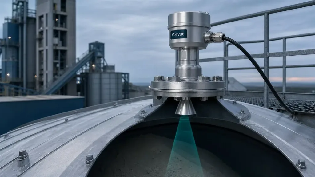
Reliable liquid level steam foam measurement is one of the harder problems in process instrumentation, because the very conditions that make a vessel useful — heat, agitation, vapor, and surface froth — are the same conditions that degrade non-contact level signals. A clean, calm, ambient-temperature tank is forgiving; almost any technology reads it well. Add a blanket of condensing steam above the surface, or a layer of stable foam on top of the liquid, and the measurement physics change fundamentally. This article explains why ultrasonic sensing weakens in these conditions, why frequency-modulated continuous-wave (FMCW) radar holds up better, and how to choose antennas and process connections so the instrument actually survives the application. The combined ultrasonic and radar liquid level system pairs both technologies under one platform, which makes the trade-offs below practical rather than academic.
How Ultrasonic Measures Level — and Where It Breaks Down
Ultrasonic level sensing works by emitting an acoustic pulse from a transducer, then timing the echo that returns from the liquid surface. Distance is derived from the speed of sound in the gas above the liquid. Volivue ultrasonic devices cover a range of typically 0.3 to 15 m with accuracy of around ±0.25% of full scale, and they perform well on clean, vented, near-ambient liquids with low foam. The dependence on the gas medium, however, is exactly where steam and foam cause trouble.
Sound is a mechanical pressure wave that needs a stable, predictable medium to travel through. Three mechanisms degrade ultrasonic performance:
- Vapor attenuation. Steam and dense vapor absorb and scatter acoustic energy. As the echo weakens, the receiver may fail to detect a clean return, producing dropouts or erratic readings.
- Speed-of-sound drift. The speed of sound varies with temperature, humidity, and gas composition. A vessel where the headspace temperature swings, or where vapor concentration changes during a batch, shifts the effective sound velocity and biases the calculated distance unless continuously compensated.
- Foam absorption. Surface foam is acoustically soft. Instead of reflecting the pulse, a foam layer tends to absorb it, so the sensor either loses the echo entirely or, worse, reads the top of the foam as if it were the liquid surface.
None of this makes ultrasonic a poor choice in general — it remains an efficient, cost-effective technology for the right conditions. It simply means that steam, condensing vapor, and persistent foam push the application outside ultrasonic’s comfort zone. When the headspace stays calm and dry, ultrasonic is hard to beat on value.
Why FMCW Radar Stays Stable in Vapor and Foam
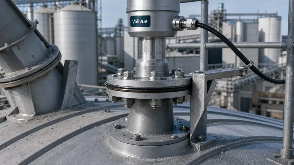
Radar level transmitters measure with microwaves rather than sound. In an FMCW design, the transmitter sweeps a microwave signal across a frequency band and compares the returning echo against the outgoing sweep; the frequency difference encodes the distance to the surface. This is the core advantage for difficult headspaces: microwave propagation is essentially independent of gas temperature, pressure, humidity, and vapor density. The FMCW radar level transmitter therefore does not need the speed-of-medium compensation that ultrasonic relies on.
Volivue radar devices span a range of typically 0.1 to 30 m, with accuracy that is model-dependent — ranging from approximately ±2 mm on higher-resolution models to a few percent on longer-range or lower-cost variants. Several properties explain the stability:
- Vapor transparency. Microwaves pass through steam and most process vapors with minimal attenuation, so a condensing or steam-filled headspace that blinds an acoustic sensor has little effect on the radar echo.
- No medium calibration. Because the signal does not depend on the speed of sound, headspace temperature swings and changing gas composition do not bias the reading.
- Strong reflection from the liquid surface. The reflection strength depends on the dielectric contrast between vapor and liquid. Water-based and conductive liquids reflect microwaves strongly, giving a robust echo even through a vapor blanket.
Radar is not magic, and the next section covers where foam can still complicate it. But for vessels dominated by steam, condensation, or volatile vapor, FMCW radar is the more stable foundation — which is why the same platform offers both branches and lets the application dictate the choice.
How Foam Type Affects Radar — Light, Wet, and Dense
Foam is more nuanced for radar than vapor is. Where steam is largely transparent to microwaves, foam can interact with the signal in different ways depending on its physical structure, and the outcome ranges from negligible to significant. It helps to think in three categories:
- Light, dry foam. Thin, airy foam with large bubbles and low water content is mostly transparent to microwaves. The radar signal passes through and reflects off the true liquid surface beneath, so the measurement is generally reliable.
- Wet, conductive foam. Foam with high water content and conductive properties reflects part of the microwave energy at the foam surface and attenuates the rest. This can pull the reading toward the foam top or weaken the liquid echo, and is the most challenging case.
- Dense, stable foam. Thick, persistent foam layers — common in fermentation and some cleaning cycles — sit between the two extremes and depend heavily on water content and bubble size.
Two practical levers improve radar behavior under foam. First, antenna and frequency selection: the right antenna geometry concentrates energy and improves the signal-to-noise ratio against a foam layer. Second, signal processing in the transmitter — echo tracking and false-echo suppression — helps the instrument distinguish the genuine liquid return from foam-surface reflections. Where foam is severe and persistent, no non-contact technology is fully immune, and a guided or contacting approach may be considered; but for the common light-to-moderate foam encountered in many process vessels, FMCW radar with an appropriate antenna remains dependable.
Choosing the Antenna and Process Connection
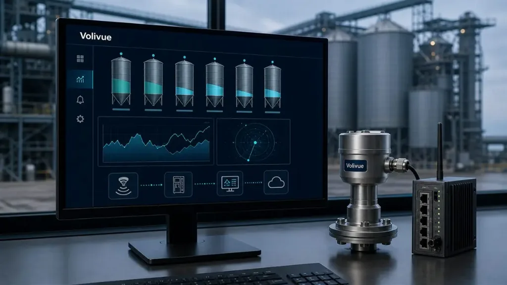
In steam and foam service, the antenna and the process connection are as decisive as the underlying technology. A correctly specified radar in the wrong mechanical configuration will still struggle. Consider these factors when configuring the instrument:
- Antenna type. Horn antennas offer a focused beam and strong signal gain, which helps in tall or vapor-heavy vessels and against foam. Where condensation, buildup, or aggressive cleaning is a concern, a flush or encapsulated antenna with a low-fouling face is preferable because it resists product accumulation that would otherwise distort the echo.
- Beam angle and obstructions. A narrower beam avoids agitators, heating coils, baffles, and vessel walls that would otherwise generate false echoes. Aim the beam at a clear path to the surface, away from inlet streams and internal structures.
- Process connection and sealing. Steam service implies elevated temperature and pressure at the connection. Select a flange or threaded connection with seals and process-isolation rated for the worst-case temperature and pressure, and confirm the variant suits the medium.
- Temperature isolation. A high-temperature extension or thermal isolator between the process and the electronics protects the transmitter from a hot, steamy headspace and extends service life.
- Hygienic and CIP needs. Vessels subjected to clean-in-place cycles need crevice-free, cleanable connections and an antenna that tolerates hot caustic or acidic wash without retaining residue that would compromise the next batch.
Across all of these, environmental sealing matters: Volivue level instruments offer IP67 and IP68 ingress protection, and hazardous-area variants are available depending on the model and the zone classification of the installation.
Typical Scenarios: Condensate, CIP, and Fermentation
Three application families illustrate how the technology choice plays out in practice.
Condensate and steam-related vessels. Condensate receivers, flash tanks, and deaerators run with a hot, steam-saturated headspace and frequent condensation. Acoustic signals attenuate badly here, and the changing vapor density biases speed-of-sound calculations. FMCW radar reads through the vapor and is the more stable choice; a horn antenna with a high-temperature isolator keeps the electronics protected from the hot zone.
Clean-in-place (CIP) systems. CIP skids cycle hot water, caustic, and acid through process equipment, often generating steam and transient foam during wash and rinse phases. The instrument must survive thermal and chemical cycling and ride through short-lived foam without latching onto a false echo. A radar transmitter with a cleanable, low-fouling antenna and robust false-echo suppression handles the transient conditions well, while hygienic connections keep the installation sanitary.
Fermentation and digestion tanks. Fermenters, bioreactors, and anaerobic digesters routinely build dense, stable foam, and many also run warm with active vapor. This is the most demanding combination for non-contact level. FMCW radar with a focused antenna and good signal processing is generally the better performer; for the densest, most persistent foam, the foam type should be assessed case by case, and the antenna and beam path chosen accordingly. Outputs — 4–20 mA, HART, RS485 Modbus, or relay — integrate the reading into the plant control system regardless of which branch is selected.
In short, the more a vessel trends toward steam, condensation, and persistent foam, the stronger the case for FMCW radar; the cleaner and calmer the headspace, the more attractive ultrasonic becomes on cost and simplicity. Matching the technology to the headspace, then specifying the antenna and process connection to suit, is what produces a measurement that holds over the life of the installation.
To scope a specific vessel or compare both technologies against your process conditions, talk to our measurement engineers with your application details.
—
Related reading: level sensing selection guides in Technical Insights