 EN
EN 中文
中文 ES
ES RU
RU FR
FR PT
PT AR
AR DE
DEFMCW Radar Level Measurement in High-Temperature, High-Pressure Service
Hot, pressurized vessels are some of the most demanding environments in process plants. Steam columns shift the apparent distance to a liquid surface, condensate films coat any wetted part, and thermal cycling stresses every seal in the signal path. For these duties, high temperature radar level measurement using a non-contact FMCW (Frequency-Modulated Continuous Wave) sensor has become the default choice, because the microwave beam reaches the surface without a probe ever touching the medium. This article explains how the technology behaves under heat and pressure, why the sealed antenna and process connection matter so much, and how to read level reliably across steam condensation, heat-exchange, and pressurized-reaction duties.
The reference instrument throughout is the Volivue Radar Liquid Level Transmitter, a non-contact FMCW microwave level transmitter built with high-temperature and high-pressure variants available by model.
Why Non-Contact Radar Beats Contact Methods in Hot, Pressurized Vessels
Contact technologies — guided-wave radar probes, capacitance rods, displacers, and float systems — all place hardware inside the medium. In hot, pressurized service that hardware becomes a liability. Coating, scaling, and thermal expansion change a probe’s electrical or mechanical response over time, and any internal component is exposed to the full process temperature and pressure.
A non-contact FMCW radar avoids those failure modes. The transmitter sits above the surface and sweeps a microwave signal across a frequency band; the echo returning from the liquid is mixed with the outgoing sweep to produce a beat frequency proportional to distance. Because the measurement is electromagnetic and the only process-exposed parts are the antenna and the seal, there is no mechanical wear, no moving part to seize, and nothing for product to build up on in the beam path.
This matters most where the medium is aggressive or the duty cycle is harsh. Microwaves penetrate vapor, light foam, and the temperature gradients above a boiling liquid, so the reading stays stable when optical or contact methods would drift. For a broader comparison of sensing principles, the 80 GHz solid radar level sensor covers the high-frequency, narrow-beam end of the same product family for powders and bulk solids.
The Sealed Antenna and Process Connection: The Real Pressure Boundary
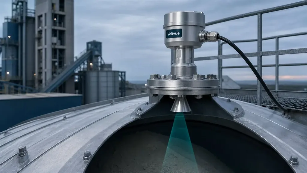
In a pressurized vessel the antenna assembly is not just a transmitting element — it is part of the pressure boundary. Everything depends on how cleanly the microwave signal can cross from the electronics into the vessel while heat and pressure are kept on the process side.
The Volivue transmitter uses a sealed antenna so the wetted interface can withstand high pressure, elevated temperature, and corrosive vapors. The seal does two jobs at once: it contains process pressure and it provides a microwave-transparent window so the FMCW sweep passes through without excessive attenuation. Wetted materials are selectable by model — 316L stainless steel, PTFE, or PVDF — so the interface can be matched to the chemistry of the medium rather than forced into a single compromise.
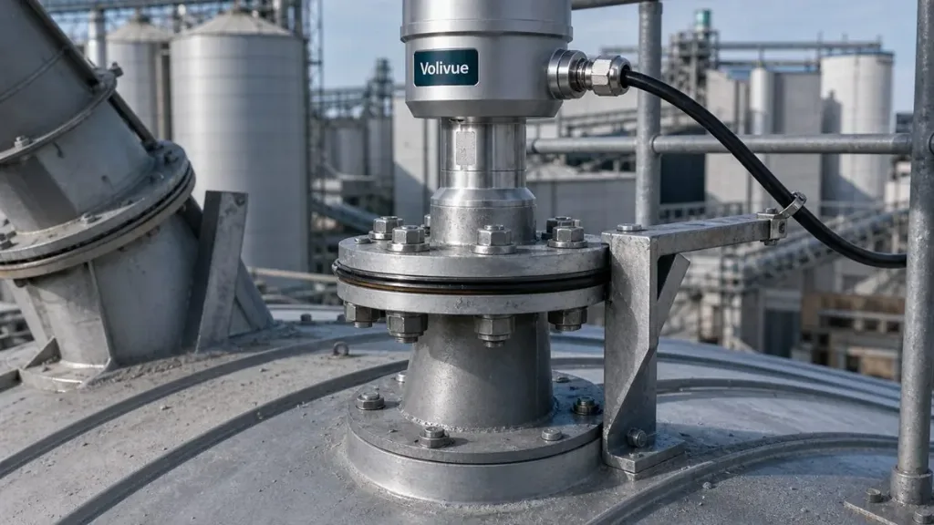
The process connection completes the boundary. A high-pressure flange variant is available by model, allowing the instrument to be rated for the vessel’s design pressure and bolted to a standard nozzle. Selecting the flange to match the vessel class, gasket, and bolting keeps the rated pressure boundary continuous from the vessel wall through to the sealed antenna, which is exactly what hot, pressurized service requires.
High-Temperature and High-Pressure Variants: Matching the Instrument to the Duty
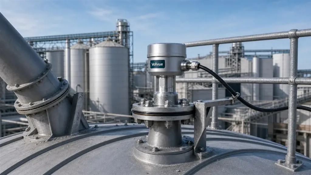
There is no single transmitter that suits every hot or pressurized vessel, which is why the variants matter. A high-temperature variant adds thermal isolation between the hot process connection and the temperature-sensitive electronics, so the sensing module stays within its operating window while the antenna sees the full vessel temperature. A high-pressure flange variant provides the mechanical rating and sealing arrangement for elevated pressure.
These options are specified by model rather than universal, so the right approach is to define the duty first: peak and continuous process temperature, design and operating pressure, the medium’s chemistry, and whether vapor or foam is present. From there the wetted material (316L, PTFE, or PVDF), the antenna and seal arrangement, and the flange rating follow. Typical liquid measuring ranges fall around 0.1 to 30 m depending on model and antenna, with accuracy on the order of ±2 mm achievable on suitable models. Treat these as model-dependent figures to confirm against the specification for the variant you select, never as a blanket guarantee.
Outputs are consistent across the variants: 4–20 mA, HART, RS485 Modbus, and a relay option cover most control and indication schemes, and enclosure protection to IP67/IP68 suits washdown and outdoor nozzles. Where the vessel sits in a classified area, an explosion-protected variant is available by model and must be selected to match the area classification recognized on site.
How Temperature and Pressure Affect the Measurement — and How to Compensate
Heat and pressure do influence a radar reading, but the effects are well understood and largely correctable. The dominant factor in hot, pressurized vessels is the vapor space above the liquid. As temperature and pressure rise, the vapor — typically steam — becomes denser, and a denser vapor slows the microwave signal slightly. Because FMCW infers distance from signal travel, a slower beam makes the surface appear farther away than it is, biasing the level low if left uncorrected.
Vapor-pressure (gas-phase) compensation addresses this. By accounting for the vapor’s density as a function of process temperature and pressure, the calculated distance is corrected back to the true surface position. In saturated-steam service the relationship between temperature, pressure, and vapor density is predictable, so the correction can be applied reliably once the operating envelope is known.
Two secondary effects round out the picture. First, thermal expansion of the vessel and nozzle shifts the physical reference point; for tall hot vessels this is worth accounting for during calibration. Second, condensate forming on the antenna seal can attenuate the signal, which is why a microwave-transparent, condensate-shedding seal and a generous link budget matter. The non-contact design keeps these as manageable corrections rather than the drift-and-recalibrate cycle that contact sensors suffer in the same conditions.
Typical Hot and Pressurized Applications
Steam condensation and steam drums. Boiler drums, deaerators, and flash vessels run with a hot, condensing vapor space directly above the liquid. The sealed high-temperature antenna tolerates the heat while gas-phase compensation removes the steam-induced bias, giving a stable level even as load and pressure swing.
Heat-exchange and thermal-cycling service. Reboilers, evaporator sumps, and jacketed vessels see large, repeated temperature swings. A non-contact transmitter has nothing inside the medium to fatigue or coat, so it holds calibration far better than a probe exposed to the same cycling, and the thermal isolation in the high-temperature variant protects the electronics.
Pressurized and reaction vessels. Autoclaves, pressurized reactors, and surge drums combine elevated pressure with aggressive chemistry. Here the high-pressure flange variant carries the rated pressure boundary, while a PTFE or PVDF wetted material handles corrosive media. The microwave beam reads through foam and vapor that would blind optical or contact methods.
In each case the engineering decisions trace back to the same chain: confirm the duty, select the variant and wetted material, set the flange to the vessel rating, and apply vapor compensation tuned to the operating envelope.
Selecting and Specifying with Confidence
High temperature radar level measurement is reliable when the instrument is matched to the duty rather than dropped onto a nozzle and left to fend for itself. Define the thermal and pressure envelope, choose the high-temperature and high-pressure variants your vessel needs, pick the wetted material for the chemistry, and plan the gas-phase compensation for the vapor space. Done this way, a non-contact FMCW transmitter delivers stable, low-maintenance level across the harshest vessels in the plant.
To scope a transmitter for a specific hot or pressurized vessel — including variant, wetted material, flange rating, and output — contact the Volivue engineering team with your process conditions.
Related reading
For more measurement-selection and process-instrumentation articles, browse the Volivue technical insights library.