 EN
EN 中文
中文 ES
ES RU
RU FR
FR PT
PT AR
AR DE
DEPump Control and Dry-Run Protection with a Level Sensor
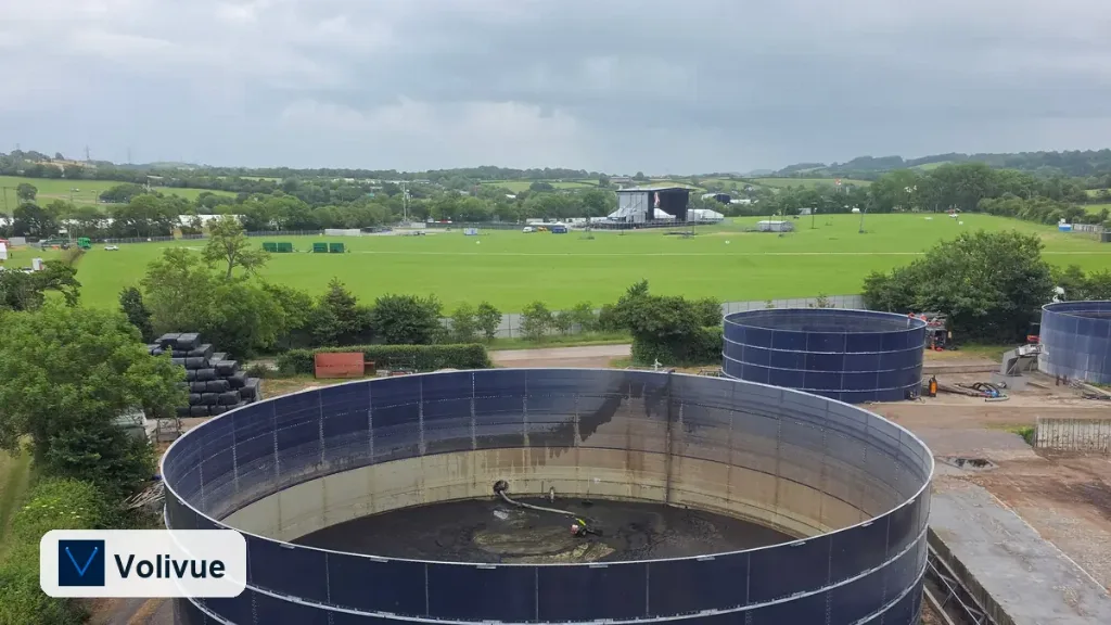
A reliable pump control level sensor is the difference between a pump station that runs unattended for years and one that burns out a motor on a quiet night shift. When level measurement drives pump start/stop directly, the control loop becomes simpler, the wiring shrinks, and the protection logic lives where the process actually is — at the tank. This article walks through how to build that loop: setting high and low thresholds, wiring relay, 4–20mA, or Modbus outputs to pump starters, adding hysteresis so contactors do not chatter, and integrating the whole arrangement with a PLC or SCADA system.
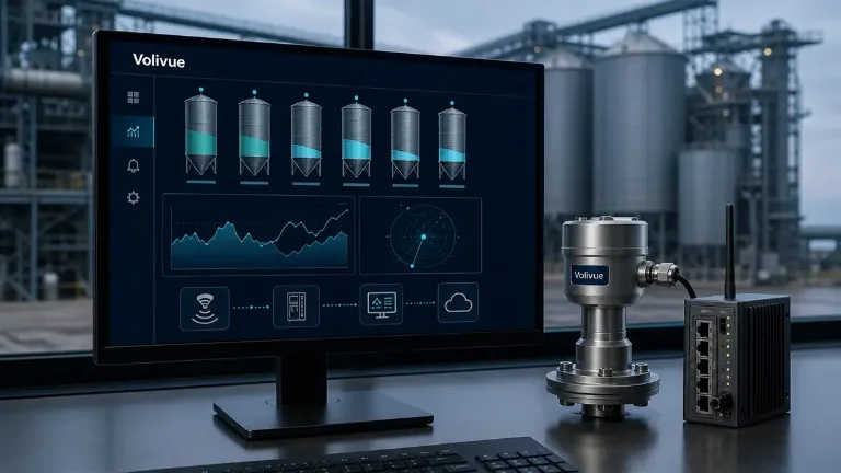
The hardware reference throughout is the combined ultrasonic and radar liquid level system, which offers both ultrasonic and radar measurement branches and the output options described below. The principles, however, apply to any level instrument that can publish a switch point or a continuous value.
Why Level-Driven Pump Control Beats Time-Based Logic
Older pump stations often ran on timers or simple float switches. Timers waste energy and risk overflow when inflow changes; bare floats fail silently when they stick or fouling holds the arm down. A continuous level instrument removes both weaknesses. It reports the real surface position several times a second, so the controller acts on what the liquid is actually doing rather than on an assumption baked into a timer.
There are two broad jobs a level sensor performs in a pump station:
- Filling control — start a pump to fill a tank, stop it before overflow. Common in process feed tanks, clean-water reservoirs, and chemical dosing supply.
- Emptying control — start a pump to draw a wet well or sump down, stop it before the pump loses suction. Common in lift stations, condensate pits, and stormwater sumps.
Both jobs share the same building blocks: a high threshold, a low threshold, a deadband between them, and an output that switches the motor. The difference is only which threshold starts the pump and which one stops it.
Setting High and Low Thresholds
A pump duty cycle is defined by two level setpoints. In an emptying application — say a sewage wet well — the high (start) level turns the pump on when liquid rises to it, and the low (stop) level turns the pump off once the well draws down. In a filling application the roles invert: the low level starts the fill pump and the high level stops it.
Place the setpoints with the sensor’s working range in mind. The ultrasonic branch of the ultrasonic and radar liquid level system measures typically across 0.3–15 m, with a near blanking zone close to the transducer face; the radar branch reaches 0.1–30 m and tolerates a smaller dead zone. Keep both the start and stop setpoints clear of the blanking distance and clear of the absolute tank bottom so the reading stays valid throughout the duty cycle.
Two practical rules:
- Reserve headroom above the high setpoint for surge, foam, and the response lag of the pump and contactor. A high-high alarm point above the start level gives a second line of defense against overflow.
- Reserve depth below the low setpoint so the pump never runs against an empty suction. The gap between the low stop point and the true minimum is your dry-run margin.
Accuracy matters most near these decision points. The radar branch resolves to ±2 mm up to ±3% depending on model, and the ultrasonic branch to ±0.25% of full scale; the exact figure is model-related, so confirm it against the datasheet for the variant you deploy and against the antenna or transducer geometry of your tank.
Wiring the Output: Relay, 4–20mA, or Modbus

The ultrasonic and radar liquid level system exposes several output paths, and each suits a different control architecture.
Relay output. The simplest, most robust option. The instrument’s onboard relay switches directly at the configured setpoint, so the relay contact can drive a motor contactor coil, a pump starter input, or a high/low alarm beacon without any intermediate controller. This is ideal for standalone stations where there is no PLC, or as a hardwired backup that operates even if the supervisory system is offline. Use the relay for the safety-critical stop — dry-run cutoff or overflow cutoff — so protection survives a network outage.
4–20mA analog. The continuous current loop reports the live level to a PLC analog input. The controller then evaluates the start and stop setpoints in software, which makes them easy to retune without touching field wiring. A 4–20mA loop also lets you trend the level, compute inflow rate, and stage multiple pumps. Because the loop is a live-zero signal, a broken wire reads below 4 mA and is detectable as a fault rather than a false “empty.”
RS485 Modbus. The digital path delivers the level value, device status, and diagnostic flags to a PLC or SCADA gateway over a two-wire bus, with multiple instruments multidropped on one cable. Modbus is the right choice when you want the controller to see not just the number but the health of the sensor — echo quality, temperature, fault registers — and when you are connecting many stations back to a central system.
A common, defensible design uses all three at once: Modbus for monitoring and trending, 4–20mA for the primary control loop, and the relay as an independent hardware interlock for dry-run or overflow. The layers do not depend on each other, so one path failing does not disable the protection.
Building Dry-Run and Overflow Protection
Dry-run protection stops a pump before it runs without liquid and overheats its seals or bearings. Overflow protection stops a fill before the tank spills. Both are threshold actions, and both deserve a dedicated, independent trigger rather than sharing the normal duty setpoint.
For dry-run protection on an emptying pump, define a protection level below the normal low stop point. If the level ever falls to it — because inflow stopped, a valve closed, or the duty stop point drifted — the controller (or the instrument relay) cuts the motor immediately and raises an alarm. The protection point should sit above the suction inlet so the pump is denied before it actually loses prime.
For overflow protection on a filling pump, define a high-high level above the normal stop point. Reaching it forces the pump off and signals an alarm regardless of what the duty logic is doing.
Two design notes keep these from nuisance-tripping:
- Drive the protection action from the relay output wherever possible, so it remains active during a PLC reboot or a SCADA dropout.
- Apply a short, deliberate confirmation delay (a few seconds) so a single foam-induced or splash-induced reading does not trip the interlock — but keep the delay short enough that real dry-run is caught before damage.
Setting Hysteresis to Stop Contactor Chatter
Hysteresis — the deadband between the start and stop levels — is what prevents a pump from cycling rapidly when the surface sits right at a single setpoint. Without it, ripples, turbulence, or a slow inflow that matches pump capacity would switch the contactor on and off many times a minute, wearing out the starter and overheating the motor.
The deadband must be wide enough that the level moves meaningfully between switch points. Sizing depends on three things:
- Pump flow versus tank cross-section — a small tank with a large pump empties or fills fast, so even a modest deadband gives a comfortable run time.
- Acceptable starts per hour — motor and contactor ratings cap how often a pump should cycle. Widen the deadband until the worst-case cycle count falls under that limit.
- Surface stability — turbulent wells and foaming liquids need a larger deadband, plus signal damping in the instrument, so noise does not eat into the band.
When the setpoints live in a PLC reading the 4–20mA loop, hysteresis is a software comparison with separate “above start” and “below stop” thresholds. When the ultrasonic and radar liquid level system relay switches directly, configure its on and off points to create the same band in hardware. Either way, verify the actual run time and starts-per-hour during commissioning, then adjust the band rather than assuming the calculated value is correct under live process conditions.
Integrating with PLC and SCADA
In a supervised plant the level instrument is one node in a larger control picture. A clean integration keeps the field-level protection independent while still giving the operator full visibility.
A typical arrangement:
- The 4–20mA signal lands on a PLC analog input. The PLC holds the duty start/stop setpoints, sequences lead/lag pumps, and computes inflow and pump-run statistics.
- The RS485 Modbus link carries the level value plus diagnostics to the SCADA layer, so operators see trends, alarm history, and sensor health on the HMI. For radar variants, antenna and echo diagnostics surfaced over Modbus help distinguish a real level event from a process disturbance.
- The instrument relay is wired as a hardwired interlock to the motor circuit, independent of the PLC, providing dry-run or overflow cutoff even when the controller is being serviced.
This split — software for control intelligence, hardware for last-line protection — is the pattern that survives audits and outages. The PLC can be reprogrammed, the SCADA server can be rebooted, and the pump is still protected.
For a single instrument that needs to do both ultrasonic and radar measurement and offer all of these outputs, review the ultrasonic and radar liquid level system; for narrower point applications, the standalone ultrasonic level sensor or the radar level transmitter can serve a single threshold or a single loop.
Putting the Loop Together
A dependable pump station built around a level sensor comes down to a short checklist: choose setpoints that respect the sensor’s working range and accuracy, separate the duty start/stop from independent dry-run and overflow protection, size hysteresis against real run-time and starts-per-hour limits, and split the architecture so software handles control while a hardware relay guarantees protection. Done this way, the station runs unattended, the motor is shielded from dry running, and the supervisory system sees everything it needs without owning the safety interlock.
If you are specifying a station and want help matching the measurement branch, output mix, and protection layout to your tank geometry and pump duty, talk to our measurement engineers with your application details and we will work through the setpoints and wiring with you.
—
Related reading: explore more sizing, integration, and protection guides in the Technical Insights library.