 EN
EN 中文
中文 ES
ES RU
RU FR
FR PT
PT AR
AR DE
DEReactor Level Measurement in Sealed Process Vessels
Reactor level measurement is one of the hardest jobs in process instrumentation. A sealed reactor or pressurized process vessel cannot be opened for a manual dip, the contents may be hot, corrosive, or under vacuum, and an agitator keeps the surface in constant motion. Yet the level reading drives charging, reaction control, and safety interlocks, so it has to stay trustworthy through every batch. This article looks at why closed vessels are so difficult to gauge, where older techniques struggle, and how non-contact FMCW radar earns its place on the nozzle.
Why Sealed Vessels Defeat Simple Methods
An open tank gives you options: a sight glass, a float, even a calibrated dip. A sealed reactor takes most of that away. The vessel is closed to hold pressure or vacuum, to contain solvent vapor, or to keep an inert blanket over a reactive charge. Nothing inside is accessible while the process runs, and opening a manway mid-batch is rarely safe and never quick.
Pressure and temperature add a second layer of difficulty. Many reactors cycle between vacuum and several bar of overpressure within a single batch, and jacket or coil heating can push the headspace well above ambient. Any measuring device mounted on the vessel has to keep its seal across that whole envelope, batch after batch, without letting process media migrate into the instrument.
Then there is the chemistry. Reactors handle solvents, acids, monomers, and slurries that attack ordinary wetted materials. A technique that needs a sensing element down in the liquid inherits every coating, crystallization, and corrosion problem the process can produce. Each of these factors on its own complicates the measurement; together they rule out a long list of conventional approaches and steer the choice toward an instrument that can read through a nozzle without touching the contents.
Agitators and Internals: The Real Disruptors
The defining feature of a reactor is that the contents are stirred. An agitator throws up a vortex, a sloping surface, splashing, and entrained gas, so the level is never a flat, still mirror. A measuring principle that assumes a calm surface will chase every blade pass and report noise instead of inventory.
Internals make it worse. Baffles, dip tubes, heating coils, draft tubes, and thermowells crowd the vessel and sit directly in the path of many sensors. A guided or mechanical device can foul on them; a beam-based device can pick up false echoes from them. Reading a true liquid level in that clutter demands a method that stays focused on the surface and rejects returns from fixed structures.
Mounting geometry is the third constraint. Reactors are often tall and narrow, the only free nozzle may sit off-center or close to the wall, and the agitator drive can dominate the vessel top. The instrument has to work from whatever nozzle is available, with a beam tight enough to clear nearby internals and a launch design that tolerates an imperfect mounting angle.
Steam, Foam, and Vapor in the Headspace
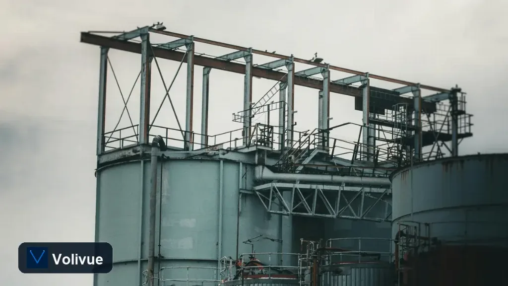
Above the liquid, a reactor headspace is rarely clean air. Solvent reactions flash vapor, exothermic steps boil off condensate, and many chemistries foam aggressively as gas evolves through a viscous charge. This is exactly the environment where contact and optical methods lose confidence.
Foam is the classic trap. A dense foam layer can read as the true surface to some sensors, or absorb the signal entirely, so the reported level drifts with foam thickness rather than with the actual liquid below it. Steam and heavy vapor add attenuation and condensation, fogging optics and coating mechanical parts.
Microwave radar handles this regime well because its energy penetrates steam, vapor, and many foams that defeat other principles, returning a measurement referenced to the liquid surface rather than the disturbance above it. Performance still depends on foam density and dielectric, so severe cases deserve an application review, but as a class, radar is far more tolerant of a turbulent, vapor-filled headspace than the alternatives.
How Non-Contact FMCW Radar Works Here
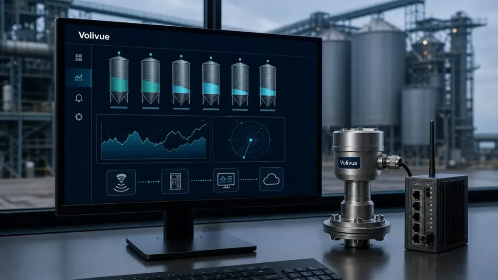
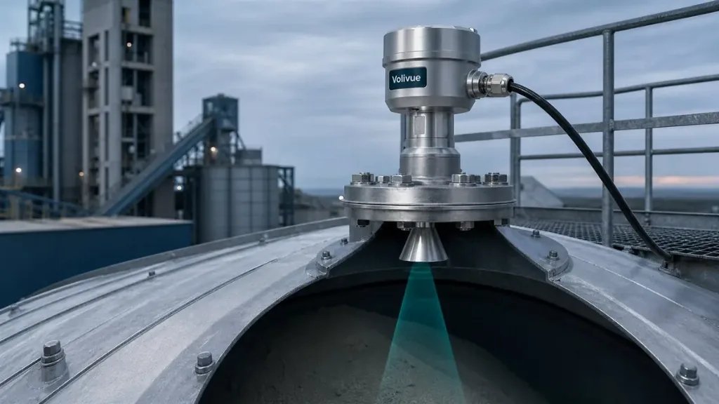
The non-contact radar liquid level transmitter addresses these conditions with a frequency-modulated continuous-wave (FMCW) radar that never touches the product. It sends a swept microwave signal down into the vessel and derives distance from the frequency difference of the reflected return, converting that into a level reading. Because nothing is immersed, there is no probe to coat, corrode, or snag on an agitator or coil.
A sealed antenna assembly is central to the design. It keeps the radar electronics isolated from the process while letting the microwave beam pass through, which is what allows the same instrument to ride through pressure swings, vacuum, elevated temperature, and aggressive vapor without breaking its seal. High-temperature and high-pressure flange variants are available by model, so the process connection can be matched to the vessel’s real envelope rather than forcing the vessel to suit the instrument.
Wetted materials such as 316L, PTFE, and PVDF are selectable to suit the chemistry, keeping the small amount of exposed hardware compatible with the solvents and acids in play. Typical performance spans a measuring range on the order of 0.1 to 30 m with accuracy on the order of ±2 mm, with tighter figures available on specific models. As always, confirm the exact range, accuracy, material, and flange rating against the datasheet for the model you intend to specify.
Process Connections and Mounting on a Reactor
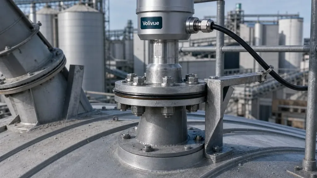
Getting the radar onto a sealed reactor is a mechanical exercise as much as an electrical one. The instrument mounts on a flanged nozzle on the vessel top, and the flange variant, by model, sets the pressure and temperature rating of that connection. Matching the flange to the existing nozzle, and to the worst-case pressure and temperature the batch will see, is the first decision in any installation.
Nozzle placement and beam alignment come next. The chosen nozzle should give the beam a clear shot to the surface, away from the agitator shaft, dip tubes, and coils wherever possible. A narrow, well-aimed beam clears nearby internals; where a perfectly clear nozzle does not exist, the antenna and electronic echo handling work together to suppress fixed reflections so a true surface return can still be tracked.
Environmental sealing closes the loop. IP67 and IP68 enclosure ratings protect the electronics in a wet, washdown-prone process bay, and Ex variants are available by model for reactors operating in flammable solvent atmospheres. Because the instrument is non-contact and externally mounted, routine inspection and replacement do not require entering or emptying the vessel.
Connectivity for Continuous Control and Safety
A reactor level reading is only useful if it reaches the control system cleanly. The transmitter offers a 4–20 mA analog output with HART for traditional loops, RS485 Modbus for digital integration, and a relay output for direct switching, so it drops into both legacy and modern reactor control schemes.
That flexibility matters because reactor level feeds several functions at once. The continuous analog value supports closed-loop charging and reaction control, the digital protocol carries the same data plus diagnostics into the DCS or PLC, and the relay can drive an independent high- or low-level alarm or interlock. In a sealed vessel where there is no backup visual check, a stable continuous reading with built-in alarm capability is a genuine safety asset, helping prevent overfill, dry-running, or running a reaction at the wrong fill level.
The practical payoff is consistency. Once the instrument is matched to the vessel, mounted, and integrated, reactor level measurement becomes a reliable input rather than a recurring uncertainty, which is exactly what batch repeatability and operator confidence depend on.
Specifying with Confidence
Closed, agitated, pressurized reactors expose the weaknesses of contact, float, and optical methods, while non-contact FMCW radar is built for precisely these conditions: it reads through steam, vapor, and many foams, ignores internals with a focused beam, and keeps its seal across the full pressure and temperature envelope. The right specification still starts with your data, so confirm range, accuracy, wetted material, flange rating, and any hazardous-area requirement against the model datasheet before you commit.
If you are sizing radar for a specific reactor or process vessel, our engineers can review the geometry, internals, and process conditions with you and recommend a suitable configuration. Request an application review.
—
Related reading: more technical insights on level measurement