 EN
EN 中文
中文 ES
ES RU
RU FR
FR PT
PT AR
AR DE
DEUltrasonic Level Installation: Blind Zone and Temperature Compensation
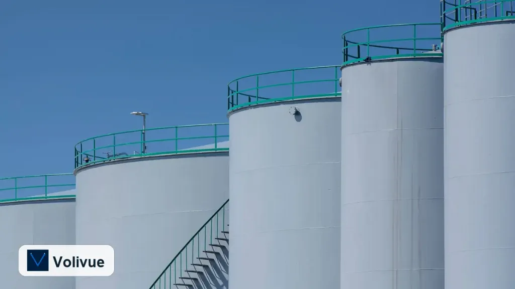
A well-specified non-contact sensor still measures poorly when the physical setup fights the measuring principle. Most disappointing field results trace back to a handful of avoidable mistakes, and getting ultrasonic level installation right means respecting two hard constraints from the start: the near-field blind zone and the way the speed of sound drifts with temperature. A Volivue Ultrasonic Liquid Level Sensor sends an ultrasonic pulse from above the liquid and times the returning echo, so anything that disturbs that echo path or changes the speed of sound changes the reading. Plan the mounting geometry and the compensation strategy together, before the bracket is drilled.
This guide walks through the blind zone and its consequences, temperature-driven speed-of-sound error and how compensation handles it, mounting height and angle, false echoes from tank walls, agitators and inflow, and a practical commissioning sequence.
How the Measurement Actually Works
The sensor emits a short burst of ultrasound and listens for the reflection from the liquid surface. Distance is calculated from the time of flight and the assumed speed of sound in the gas above the liquid. Level is then derived by subtracting that measured distance from a configured tank height or empty-distance reference.
Two facts follow directly from this. First, the transducer needs a brief recovery window after transmitting before it can listen, which creates a region near the face where no valid measurement exists. Second, the calculation assumes a speed of sound, so if the real speed differs from the assumed value, every distance reading shifts proportionally. Both effects are predictable and both are manageable once you account for them at installation.
Depending on model, a typical Volivue ultrasonic sensor measures across roughly 0.3 to 15 m, with accuracy on the order of ±0.25% of full scale and output options of 4–20 mA, RS485 Modbus, or a relay. The exact range, blind zone and accuracy figures are stated per model, so confirm them against the datasheet for the unit you select rather than assuming a single number fits every variant.
The Blind Zone and Why It Caps Your High Level
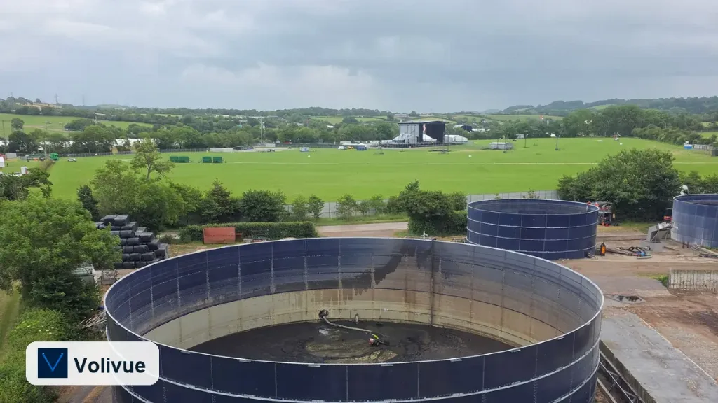
The blind zone, sometimes called the dead zone, is the span immediately below the transducer face where the sensor cannot return a reliable measurement. Echoes arriving inside this window overlap the transmit recovery period and are rejected. The practical consequence is simple but often overlooked: the highest liquid level you can measure is the maximum fill point that still sits below the blind zone, not the physical top of the tank.
If the transducer is mounted too low relative to the maximum fill, the rising surface enters the blind zone and the reading freezes, jumps, or drops out entirely near full. To avoid this, set the mounting height so that even at the highest expected level there is clearance between the liquid surface and the lower edge of the blind zone. Treat the blind-zone length as a fixed budget you must reserve at the top of the vessel.
When the application genuinely needs measurement very close to the sensor, or when the required full-fill clearance cannot be reserved, that is a signal the geometry is working against ultrasound. In tall, narrow, or near-full-to-the-flange vessels, a non-contact radar level transmitter typically offers a shorter unmeasurable zone and tolerates the geometry better.
Temperature, the Speed of Sound, and Compensation
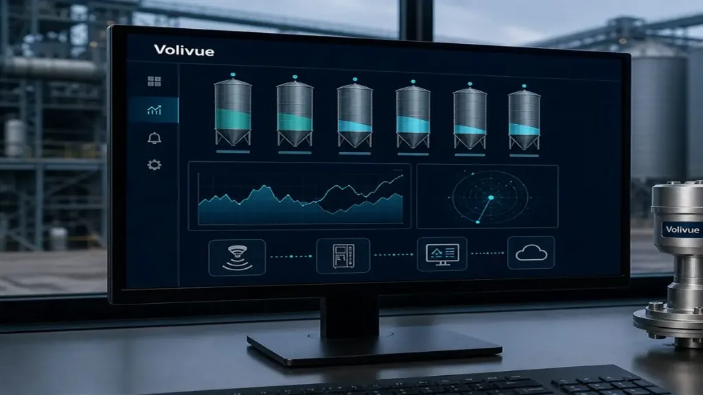
Ultrasonic distance depends on the speed of sound in the gas above the liquid, and that speed rises as the gas warms. Across the temperature swings a real vessel sees, an uncompensated reading can drift by a meaningful fraction of the distance, because the error scales with the path length. A reading taken on a cold morning and the same physical level read at midday in a sun-exposed outdoor tank will not match unless temperature is accounted for.
This is why ultrasonic sensors include temperature compensation. An onboard temperature element measures the air near the transducer and continuously corrects the assumed speed of sound, holding the distance calculation accurate as conditions change. For most installations, enabling and trusting the built-in compensation is sufficient.
The limitation to understand is that compensation works best when the sensor’s temperature element represents the whole sound path. Strong thermal gradients, such as a hot vapor layer near the surface with cool gas at the sensor, are not captured by a single point measurement and leave residual error. Mount the sensor away from direct radiant heat, avoid placing it where it reads a temperature unlike the bulk of the path, and where stratification is severe, plan for it rather than assuming compensation erases it.
Mounting Height, Angle, and Position
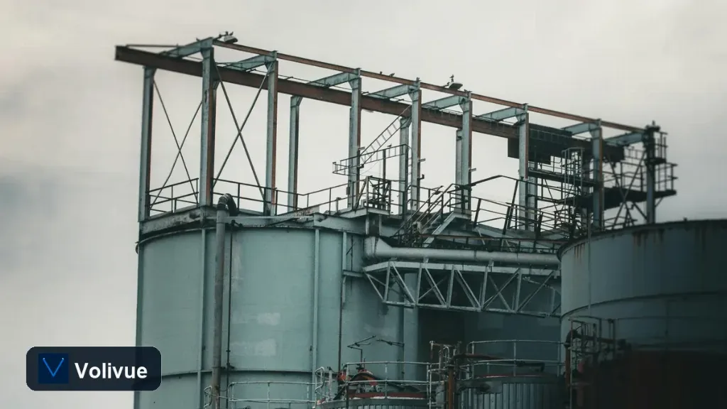
Geometry decides whether echoes come back clean. The transducer should face the liquid surface as squarely as possible, because an ultrasonic beam reflects like light off a mirror: tilt the sensor and the echo deflects away from the receiver, weakening or losing the signal. Mount perpendicular to a calm, flat surface and keep the face level.
Position the sensor away from the tank wall and away from any fixed obstruction in the beam path. The beam spreads in a cone as it travels, and anything that cone clips, a ladder, a weld seam, a baffle, a stiffening ring, a fill pipe, can produce an echo that competes with the true surface return. Keep internal structures out of the cone and respect the manufacturer’s minimum distance from the wall for the unit’s beam angle.
On a domed or sloped tank top, use a standoff or mounting plate so the face sits flat and horizontal. Avoid nozzles that are long and narrow relative to their diameter, since the inside walls of an over-long nozzle generate their own ringing echoes inside the blind-zone region. If a nozzle is unavoidable, keep it short, smooth-bored, and as wide as practical.
Avoiding False Echoes: Walls, Agitators, and Inflow
False echoes are the most common cause of unstable ultrasonic readings, and three sources dominate. Tank walls and internal fittings reflect part of the beam; the fix is beam clearance, careful positioning, and using the sensor’s false-echo mapping during commissioning to teach it which fixed reflections to ignore.
Agitators and mixers break up the surface and throw the reflection in changing directions. A turbulent or foamy surface scatters sound rather than returning a clean echo, so readings become noisy or drop out. Where stirring is intermittent, output damping or signal averaging smooths the result; where the surface is permanently disturbed or heavily foaming, ultrasound may not be the right principle and a contacting or radar approach should be evaluated.
Inflow is the third source. A stream of liquid filling the tank, or splashing within the beam cone, creates moving reflectors and a churned surface directly under the sensor. Mount the sensor away from the fill point so the beam looks at undisturbed liquid, and if necessary route the inlet to enter below the surface or against a wall to limit splashing.
Commissioning and Best-Practice Checklist
A disciplined startup turns a correct installation into a reliable measurement. Work through the following in order:
- Confirm the model’s range, blind zone and accuracy from the datasheet, and verify the maximum fill level leaves clearance below the blind zone.
- Mount perpendicular to the surface, face level, clear of walls, fill points, and in-beam obstructions; use a standoff on domed or sloped tops.
- Enter the correct empty distance and tank height so the level calculation references the right zero and span.
- Run the false-echo mapping or learn function on an empty or known-level tank so fixed reflections from fittings are suppressed.
- Enable temperature compensation and confirm the sensor is shielded from direct radiant heat that would bias its temperature element.
- Set output damping to match the process; more damping for agitated or turbulent surfaces, less for fast-responding control loops.
- Verify the output scaling against the chosen interface, whether 4–20 mA, RS485 Modbus, or relay, and confirm the engineering units and span match the receiving system.
- Validate the reading at several known levels across the range, watching especially near full where the blind zone matters most and near empty where weak echoes appear.
Respect the blind zone, trust compensation while understanding its limits, and keep the beam path clean, and a non-contact ultrasonic sensor delivers stable, repeatable level over years of service. When the geometry or the process genuinely fights the principle, recognize it early and choose the right alternative instead of fighting the physics. To match a sensor to your vessel and process conditions, request an application review with the measured tank dimensions and operating temperature range.
Related reading: explore more selection and installation guidance in our technical insights.