 EN
EN 中文
中文 ES
ES RU
RU FR
FR PT
PT AR
AR DE
DEWastewater Treatment Plant Level Monitoring: A Unit-by-Unit Planning Guide
Planning instrumentation for a municipal water resource recovery facility is rarely a single-sensor decision. A treatment train moves liquid through a dozen distinct environments, and reliable wastewater level measurement has to hold up across all of them—from a turbulent influent screen channel to a sealed, foam-covered digester. The mistake many projects make is standardizing on one sensing technology plant-wide, then fighting false echoes, condensation dropout, and chemical attack for the life of the asset.
A better approach is to map level requirements unit by unit, then assign the right technology to each. In practice that usually means a deliberate pairing of non-contact ultrasonic and radar sensing, because the two methods fail in different conditions and cover for each other. The Volivue Ultrasonic and Radar Liquid Level System was built around exactly this split: ultrasonic for clean, open, atmospheric tanks where economics matter most, and FMCW radar for the foam, vapor, and corrosion that defeat acoustic sensors. This guide walks through how to plan that mix across a typical plant.
Why one technology rarely covers a whole plant
Ultrasonic level sensors measure the time-of-flight of an acoustic pulse to the liquid surface. They are economical, non-contact, and well suited to clean water, atmospheric tanks, and open channels. A model-dependent ultrasonic instrument typically covers a measuring range on the order of 0.3–15 m with accuracy around ±0.25% of full scale. The trade-off is physical: sound travels through air, so heavy foam, dense vapor, steam, and steep temperature gradients can absorb or bend the pulse and degrade the reading.
Radar level transmitters using FMCW (frequency-modulated continuous wave) technology measure with microwaves instead of sound. Microwaves are largely unaffected by vapor, temperature swings, and most foam, and they tolerate condensation on the antenna far better than acoustics. A model-dependent radar instrument typically spans a range on the order of 0.1–30 m with accuracy in the ±2 mm to ±3% band depending on configuration and target. That robustness is why radar earns its place on the harder vessels even though ultrasonic is cheaper to deploy.
Both technology branches in the Volivue system share the same electrical interfaces—4–20 mA, HART, RS485 Modbus, and relay outputs—and the same IP67/IP68 enclosure rating. That common output layer is what makes a mixed fleet practical: the SCADA or PLC integration looks identical regardless of which sensing principle sits behind a given tag.
Mapping level requirements across the treatment train
Before selecting hardware, it helps to characterize each measuring point by the conditions that actually break sensors: surface turbulence, foam, vapor or condensation, corrosive atmosphere, whether the vessel is open or sealed, and the required range. The sections below group the common units and indicate where ultrasonic economics win and where radar robustness is worth the premium.
Influent works: screens, grit, and the wet well
The influent end is turbulent, often greasy, and prone to splashing, but it is usually open to atmosphere and free of heavy chemical vapor. Wet-well and lift-station level is the classic ultrasonic application: a non-contact sensor mounted above the maximum liquid line tracks the surface for pump start/stop control without contacting screenings or rags. A model-dependent ultrasonic level sensor handles these ranges comfortably and keeps influent instrumentation costs down across what is often a high sensor count.
Where the screen channel produces persistent splashing foam or the wet well is enclosed and develops hydrogen sulfide vapor, radar is the safer pick. The decision point is simple: if the atmosphere above the liquid is clean air, default to ultrasonic; if it is foam, vapor, or a sealed headspace, move to radar.
Open-channel flow measurement
Plants frequently meter flow through a flume or weir at the influent and effluent. Ultrasonic is the dominant technology here, because flume and weir flow is computed from a clean, open-channel head measurement—exactly the clean-water, atmospheric condition ultrasonic does best. Mounting the sensor over the stilling well and applying the flume’s head-to-flow curve gives a cost-effective primary flow signal without an in-stream device. This is one of the strongest economic arguments for keeping ultrasonic in the plant mix rather than going radar-only.
Settling and aeration: clarifiers and aeration basins
Primary and secondary clarifiers are large, relatively quiet, open basins. Their slow, broad surfaces suit ultrasonic level measurement for sludge-blanket headroom and overflow margin, again favoring the lower-cost technology. Aeration basins are the dividing line: diffused-air agitation and biological activity can throw up a persistent foam layer that scatters acoustic pulses. Where foam is light and intermittent, ultrasonic still works; where a stable foam blanket forms, an FMCW radar transmitter reads through it far more reliably.
Sludge handling and digesters
Thickeners, holding tanks, and especially anaerobic digesters are the harshest level points in the plant. Digesters are sealed, run warm, generate corrosive biogas, and frequently carry a foam cap. This is squarely radar territory: the microwave signal is indifferent to the vapor-laden headspace and tolerates condensation that would blind an acoustic sensor. For a closed digester or a covered sludge tank, a radar level transmitter is the appropriate default rather than the exception.
Chemical dosing and reuse storage
Chemical storage and metering tanks—coagulant, polymer, hypochlorite, alkalinity adjustment—are smaller but unforgiving. Aggressive vapors and the need for repeatable inventory readings push these toward radar, whose non-contact microwave measurement avoids exposing sensitive electronics to the chemical atmosphere while holding tight accuracy on a short range. Reclaimed-water and reuse storage, by contrast, is typically clean and atmospheric, so it returns to the ultrasonic column. The pattern repeats throughout the plant: clean and open favors ultrasonic economics, sealed or chemically hostile favors radar robustness.
Turning level signals into control: pumps, overflow, and dry-run protection
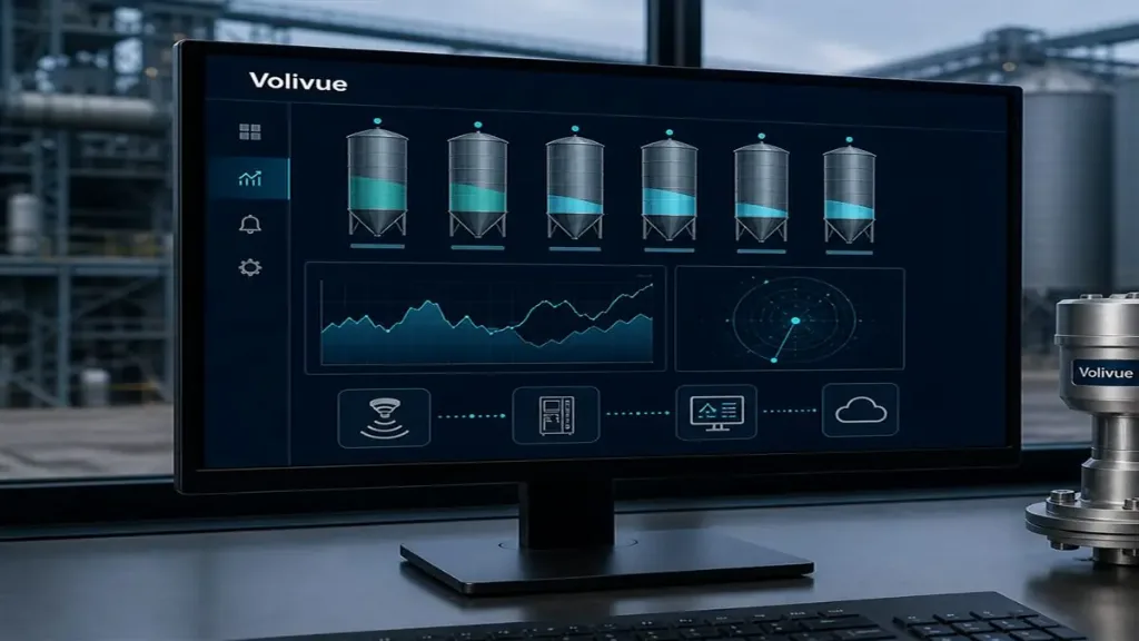
Level instrumentation only earns its keep when it drives action. Three control functions account for most of the value in a treatment plant, and all three rely on the same shared output layer described earlier.
Pump control. Wet wells, lift stations, and intermediate sumps use level to start and stop pumps within a defined band. The instrument’s relay outputs can switch duty and lag pumps directly for simple stations, while the 4–20 mA or Modbus signal feeds the PLC for variable-speed and alternation logic at larger ones. Consistent interfaces mean an ultrasonic wet-well sensor and a radar digester sensor present identical signals to the control system.
Overflow and high-level protection. A high-high level threshold protects against sanitary sewer overflows and basin spillage. Configuring a dedicated relay trip independent of the analog control loop gives a hardwired alarm and pump-trigger path that does not depend on the SCADA scan, an important layer for regulatory-sensitive overflow points.
Dry-run protection. Low-low level interlocks stop pumps before they cavitate or run dry against an empty well or storage tank. The same low threshold can hold a dosing pump off until reagent is available. Because the sensor reports a continuous level rather than a single switch point, one instrument provides the full band—high-high, control range, and low-low—instead of a stack of float switches.
A practical selection workflow
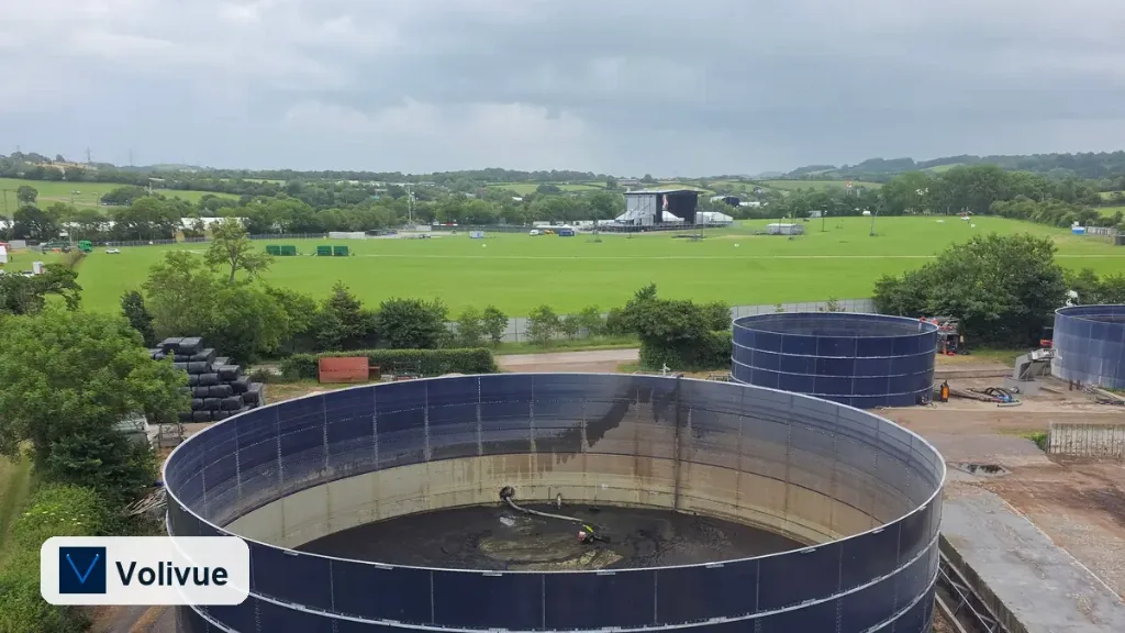
To turn this into a repeatable plan, work each measuring point through a short checklist. First, describe the atmosphere above the liquid: clean air points to ultrasonic, while foam, vapor, or a sealed headspace points to radar. Second, confirm the required range falls within the model-dependent envelope for the chosen branch. Third, note the corrosion exposure—chemically aggressive headspaces favor non-contact radar. Fourth, fix the control role—continuous control, overflow trip, or dry-run interlock—so the right output (analog, Modbus, or relay) is wired from the start. Because both technologies share interfaces and IP67/IP68 protection, you can optimize each point on its own merits without fragmenting your integration or spares strategy.
The result is a plant where the cheaper acoustic technology covers the many clean, open, atmospheric points, and radar is reserved for the foam, vapor, corrosion, and sealed vessels where it genuinely pays for itself. That balance is the core idea behind pairing the two branches rather than forcing one everywhere.
If you are scoping level instrumentation for a treatment plant or a specific unit, request an application review with your unit list, tank conditions, and control requirements, and we will help map the ultrasonic and radar mix to your process.
Related reading
For deeper guidance on matching sensing technology to process conditions, see the Volivue technical insights library.