 EN
EN 中文
中文 ES
ES RU
RU FR
FR PT
PT AR
AR DE
DELow Dielectric Radar Level Measurement: Solving Weak Echo in Powders

Few measurement problems frustrate plant engineers as consistently as a silo full of fly ash, plastic pellets, or ultrafine powder that a level instrument simply refuses to track. The material is right there, the sensor is mounted, the wiring checks out — yet the reading drifts, freezes, or jumps to the empty distance. In most of these cases the root cause is not a faulty device but a fundamental physics constraint: low dielectric radar level measurement is genuinely difficult because these materials reflect very little of the radar energy aimed at them. Understanding why the echo is weak, and what an instrument has to do to recover it, is the difference between a gauge that fights you for years and one that quietly does its job.
This article walks through the physics of weak reflections, the specific challenges low-permittivity bulk solids present, and how an 80 GHz FMCW approach — narrow beam, high frequency, and strong digital signal processing — improves reliability where lower-frequency or contacting technologies struggle. We also cover antenna selection, false-echo suppression, and the installation details that decide whether a marginal echo becomes a stable measurement.
Why Low Dielectric Materials Return a Weak Echo
A non-contact radar gauge works by transmitting a microwave signal toward the product surface and measuring the portion that reflects back. How much energy returns depends heavily on the material’s dielectric constant (relative permittivity, εr). A high-permittivity medium such as water (εr around 80) behaves almost like a mirror and reflects a strong, easy-to-detect echo. The bulk solids that cause trouble sit at the other end of the scale: many plastic pellets, fly ash, and certain ultrafine powders have effective dielectric values in roughly the 1.5 to 3 range, and the loosely packed, air-filled surface lowers the effective permittivity even further.
The reflected signal strength scales with the dielectric contrast at the surface. As εr falls toward the value of air, the reflection coefficient drops sharply, and only a small fraction of the transmitted energy comes back to the antenna. Three compounding effects make this worse in real silos:
- Surface scattering. Powders and pellets present a rough, irregular, often angled surface (a cone of repose during filling, a crater during discharge). Instead of returning one clean specular reflection, the energy scatters in many directions, so even less reaches the antenna.
- Penetration and partial transmission. With low-permittivity, low-loss media, some microwave energy passes into the bulk rather than reflecting at the top surface, spreading the return over a less defined boundary.
- Dust and product loading. During pneumatic filling, airborne dust attenuates the beam on both the outgoing and return paths, temporarily weakening an already faint echo.
The practical consequence is a low signal-to-noise ratio. The true surface echo can be smaller than reflections from internal structures, weld seams, or the wall — which is exactly when a gauge loses lock and reports a false level.
Why 80 GHz FMCW Improves Weak-Echo Performance

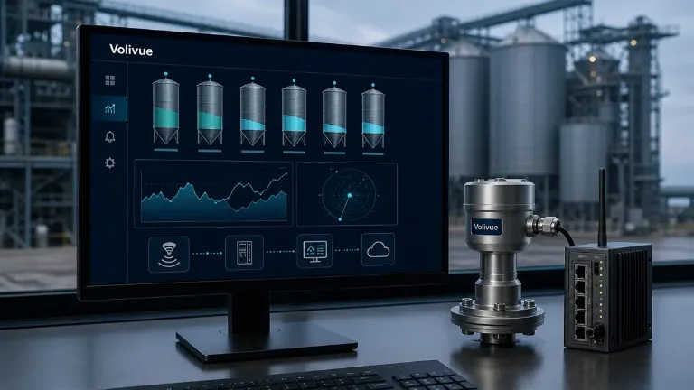
A higher operating frequency does not magically make a low-dielectric surface more reflective, but it changes the geometry and processing budget in ways that matter for weak echoes. The Volivue 80 GHz Radar Level System uses 80 GHz FMCW (frequency-modulated continuous wave) sensing with a narrow beam of roughly 3 degrees, and that combination addresses the weak-echo problem from several directions. You can review the full technical specification on the 80 GHz Radar Level System product page.
A narrow beam concentrates the available transmit energy onto a small footprint on the product surface instead of spreading it across the whole silo cross-section. For a faint reflector, focusing the energy raises the density of power hitting the target and, in turn, the strength of the return. The same narrow beam keeps the signal away from the silo wall, internal ladders, fill pipes, and structural members, so the weak true echo is not buried beneath strong nuisance reflections from the tank.
FMCW signal processing contributes the rest of the margin. Rather than relying on a single short pulse, an FMCW sensor transmits a continuous swept signal and resolves distance in the frequency domain. This yields a high inherent dynamic range and lets the instrument integrate energy over the sweep, pulling a genuine surface echo out of the noise floor where a simpler detector would miss it. With strong digital processing, the sensor can track a small, moving echo as the level changes and reject returns that do not behave like a product surface.
The net effect for low dielectric radar level applications is a usable measurement on materials that would defeat a wide-beam instrument. Volivue’s 80 GHz system covers a measurement range typically from 0.1 m up to 120 m depending on the model, with accuracy typically in the range of ±2 mm to ±3% depending on model and application — figures that hold only when the weak echo is reliably captured and processed.
Choosing the Right Antenna
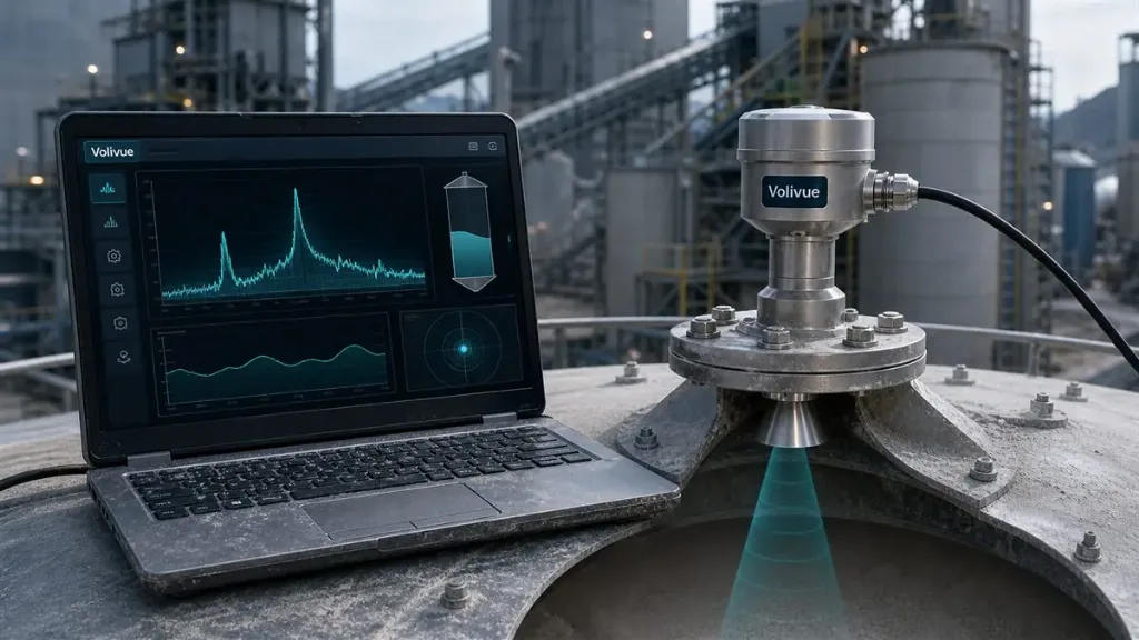
Antenna selection is the first line of defense for weak-echo materials because it sets how much energy reaches the surface and how cleanly the return is collected. The goal is the highest practical aperture and the cleanest possible mounting interface.
- Larger aperture, narrower beam. A bigger antenna produces a tighter beam and higher gain, which directly helps faint reflectors. On powders and pellets, prefer the largest aperture the process connection and nozzle allow.
- Lens or encapsulated horn antennas are well suited to dusty silos. A flush, smooth radiating face is easier to keep clean and less prone to product buildup that would attenuate the signal.
- Nozzle compatibility. A long or narrow mounting nozzle can clip the beam and create ringing that masks the true echo. Match the antenna to the nozzle length and diameter, and keep the nozzle as short and wide as the installation permits.
- Process conditions. Choose materials and seals rated for the silo’s temperature, abrasion, and chemical environment. The 80 GHz system offers IP67/IP68 enclosure protection, and hazardous-area (ATEX/IECEx) variants are available depending on the model for dust-classified zones.
When the antenna is correctly sized and cleanly coupled, the signal processing has a far better starting point, and false-echo suppression becomes a fine-tuning step rather than a rescue operation.
Signal Processing and False-Echo Suppression
Even with a focused beam and a good antenna, a low dielectric surface produces an echo that competes with fixed reflections inside the silo. This is where commissioning the gauge correctly pays off.
The standard tool is a stored echo profile, often called a false-echo map or tank map. With the silo empty (or at a known low level), the instrument records the static reflections from nozzles, internal structures, and the wall. During operation it subtracts this map, so the processing concentrates on the moving return that represents the actual product surface. For low-permittivity materials this step is essential: without it, a strong fixed reflection can easily out-shout the genuine, weaker echo.
Beyond mapping, useful processing strategies include:
- Adaptive threshold tracking that follows the expected echo as the level rises and falls, rather than applying one fixed amplitude gate that a weak signal would never clear.
- Echo qualification by motion and consistency, so the sensor favors a return that changes coherently with fill and discharge over a static artifact.
- Damping and rate limiting to smooth the agitated surface seen during pneumatic filling without masking real, fast level changes.
For configuration and output, the 80 GHz system provides 4–20 mA, HART, RS485 Modbus, and PROFIBUS PA, so the processed level value integrates cleanly with existing PLC, DCS, or ERP/MES layers. The processing should be tuned to the application, not left at factory defaults, when the material is a known weak reflector.
Installation Practices That Protect a Weak Echo
A correctly specified instrument can still fail if it is poorly positioned. With low-permittivity materials there is no margin to waste, so installation discipline matters more than usual.
- Aim at the right point. Mount the sensor so the beam strikes the product surface as squarely as possible, avoiding the fill stream and the steepest part of the cone of repose. Angled or scattering surfaces shed even more of a weak signal.
- Keep clear of structures. Position the antenna so the beam does not graze the wall, ladders, baffles, or support beams within the beam angle. The narrow 3-degree beam helps, but it still needs an unobstructed path.
- Avoid the fill point. A beam pointed into falling product reads the stream, not the surface, and dust there is densest. Offset the mounting toward a quieter region of the silo top.
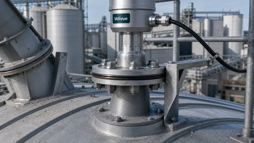
- Mind the nozzle. Use a short, wide nozzle with a smooth interior, and ensure the antenna face sits at or just below the nozzle opening so the beam clears it cleanly.
- Plan for buildup. In dusty service, choose a flush antenna face and an accessible mounting so periodic inspection or cleaning is realistic.
Get these points right and the gauge starts commissioning with the strongest weak echo the silo can offer — which is precisely the condition under which 80 GHz processing performs best.
Bringing It Together
Low-dielectric powders and pellets are hard to measure because they return little energy, scatter what they do reflect, and force the surface echo to compete with fixed reflections inside the silo. The answer is not a single trick but a coherent chain: a high-frequency, narrow-beam 80 GHz FMCW sensor to concentrate and recover the signal, an appropriately sized clean antenna, disciplined false-echo mapping and adaptive processing, and installation that gives the beam a clear, square shot at the surface. Together these turn a marginal echo into a dependable, model-dependent measurement across cement, fly ash, low-permittivity ultrafine powders, and plastic granulate.
If you are evaluating a difficult silo and want the configuration reviewed against your material and geometry, request an application review with our engineering team.
—
Related reading: Explore more field guides and measurement deep dives in our Technical Insights library.