 EN
EN 中文
中文 ES
ES RU
RU FR
FR PT
PT AR
AR DE
DEHow 80GHz FMCW Radar Measures Level Reliably Through Dust
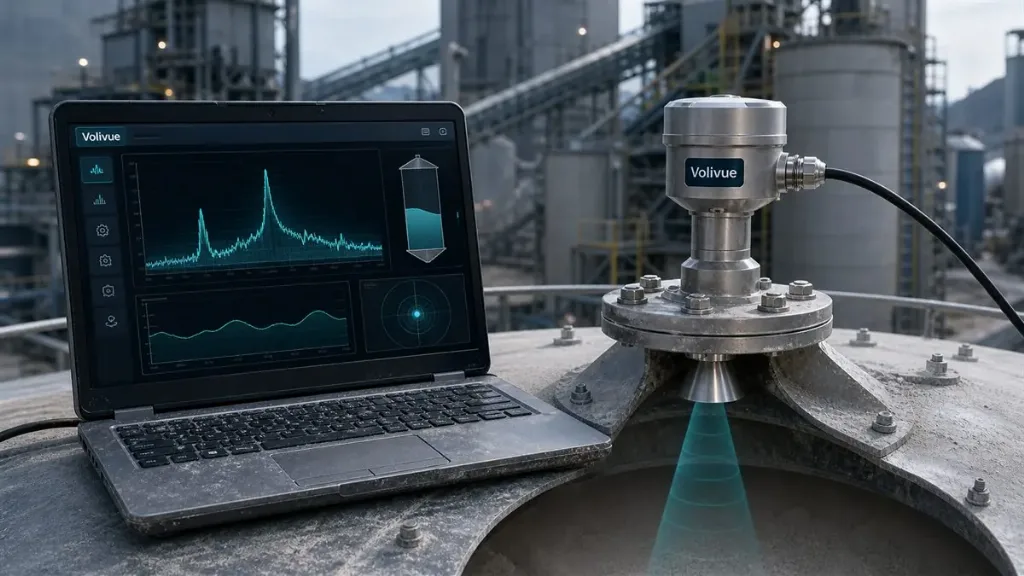
Dust is the defining obstacle for level measurement in cement, lime, and mineral processing. When a silo is filled pneumatically or by gravity, the airborne cloud above the material can be dense enough to blind many sensing technologies for minutes at a time. An 80GHz radar level instrument addresses this problem not by overpowering the dust, but by concentrating its energy into a beam narrow enough to pass through it and reach the true surface. This article explains the underlying physics: how frequency-modulated continuous-wave (FMCW) ranging works, why operating at 80GHz produces such a tight beam, and why that beam geometry is what actually lets the signal penetrate dust while ignoring wall, buildup, and internal-structure reflections.
The goal here is to give engineers a clear, vendor-neutral picture of the measurement principle before they evaluate any specific model. Performance figures cited are conservative, model-dependent ranges; always confirm exact specifications against the data sheet for the variant you intend to deploy.
What FMCW Actually Measures
A pulse radar estimates distance by timing how long a short burst takes to travel to the surface and back. Because radio waves move at the speed of light, the round trip across a silo of a few tens of meters lasts only nanoseconds, so the timing electronics must be extremely fast and the returning echo must be cleanly separable from noise.
FMCW takes a different route. Instead of emitting discrete pulses, the sensor transmits a continuous wave whose frequency is swept linearly across a band — a “chirp.” By the time the reflected chirp returns, the transmitter has already moved on to a higher frequency. Mixing the returning signal with the one currently being transmitted produces a low beat frequency that is directly proportional to the round-trip time, and therefore to distance. The instrument then measures that beat frequency in the kilohertz range rather than trying to time a nanosecond pulse directly.
This frequency-domain approach has two practical consequences. First, the hard work moves from ultra-fast timing into stable, well-understood signal processing, which improves repeatability. Second, the full spectrum of beat frequencies contains a separate peak for every reflecting object in the beam — the material surface, but also any wall feature or fixture the beam happens to clip. The processing job is to identify which peak is the real surface, and the cleaner the beam, the fewer competing peaks there are to sort through. A modern 80GHz FMCW radar level system leans heavily on this spectral clarity.
Why 80GHz Produces a Narrow Beam
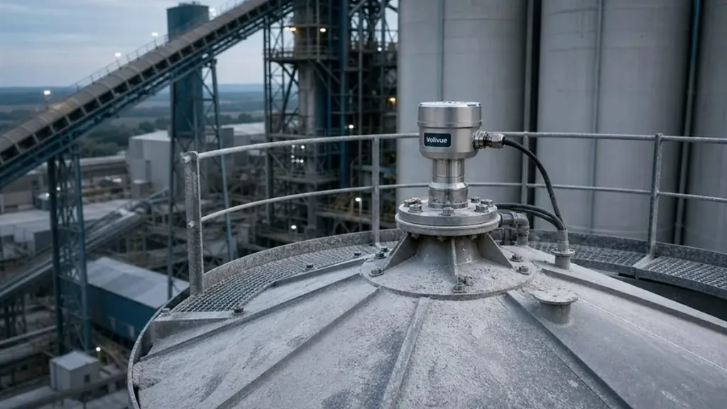
Beam width is governed by the relationship between the operating wavelength and the size of the antenna aperture. For a given antenna diameter, a shorter wavelength yields a tighter beam. At 80GHz the wavelength is roughly 3.75 mm, several times shorter than at the 26GHz band that older instruments used. That shorter wavelength is what allows a compact lens antenna to focus the energy into a beam on the order of 3 degrees.
The difference is more than cosmetic. A wider beam illuminates a large cone inside the vessel, so as the signal travels down it inevitably strikes the silo wall, weld seams, ladders, and any material clinging to the structure. Each of those surfaces sends an echo back, cluttering the spectrum with false peaks. A 3-degree beam, by contrast, projects a slender column straight down the vessel. Over a long measuring distance the illuminated footprint stays small relative to the silo diameter, so the beam reaches the material surface without grazing the walls or internal fittings.
Narrow beam geometry also simplifies installation. The instrument can be mounted off-center, angled past obstructions, or aimed into a tall, slender silo without the operator having to map out and suppress a forest of fixed echoes. Fewer false reflections in the raw spectrum means the surface peak stands out more clearly, which is the foundation of a stable reading.
How a Narrow Beam Penetrates Dust
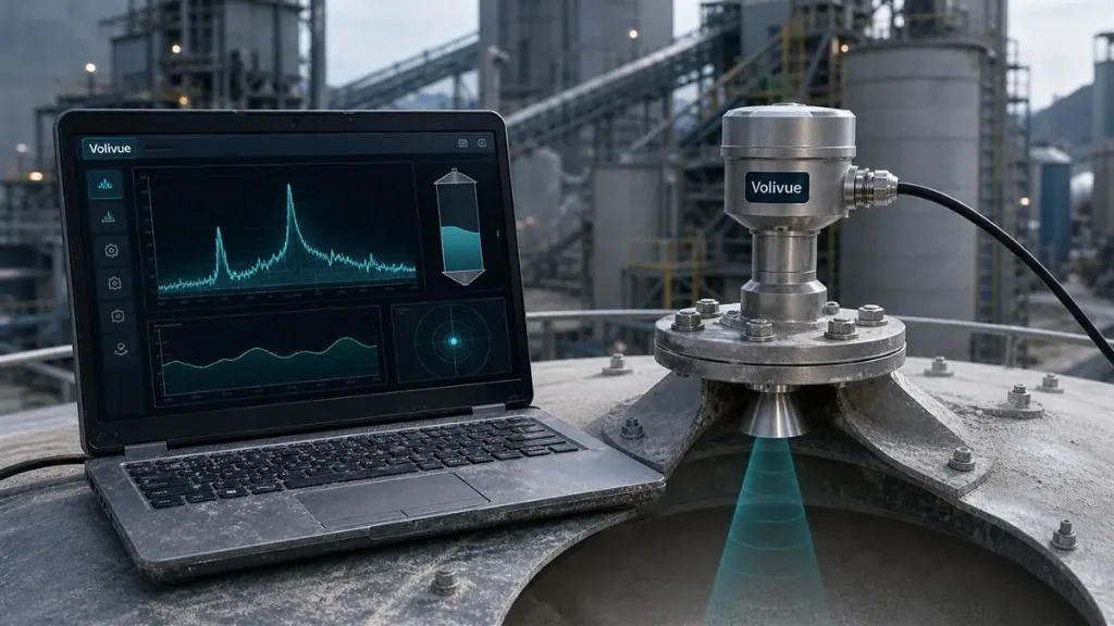
Dust degrades a measurement in two ways: it scatters and absorbs the signal, weakening the echo, and the cloud itself can produce diffuse reflections that look like a false surface. A wide beam makes both problems worse because it interacts with a larger volume of the dust cloud and collects scattered energy from a broad cone.
Concentrating the same transmit power into a 3-degree beam raises the energy density along the line of sight. More of the signal travels straight down to the real surface and straight back, rather than being dispersed sideways into the cloud. The result is a stronger, more coherent surface echo relative to the diffuse background — a better signal-to-clutter ratio precisely when filling dust is at its worst. The radar is not “seeing through” dust in a magical sense; it is delivering enough focused energy to the surface that a usable reflection survives the trip.
This is also where FMCW processing and beam geometry reinforce each other. Because the spectrum already contains few competing peaks from walls and structures, the signal processing can apply consistent tracking logic to follow the genuine surface peak even as the dust-related background rises and falls during a fill cycle. Conservative accuracy figures — typically in the range of a few millimeters up to a small percentage of distance depending on the model — hold up better when the surface echo is not buried under structural clutter.
The Non-Contact Advantage
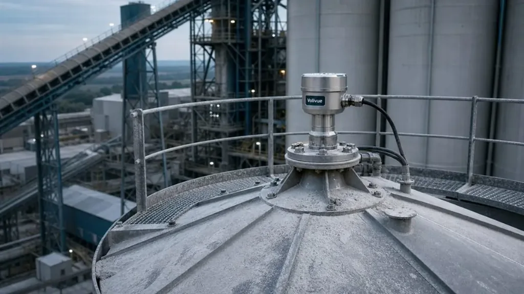
An 80GHz radar measures from the top of the vessel without any part of the instrument touching the material. Nothing hangs into the silo, so there is no probe to abrade, no cable to bury under an avalanche of incoming solids, and no mechanical element to wear out. For abrasive and dusty media — cement, lime, mineral powders, raw meal, clinker, fly ash, and low-dielectric ultra-fine powders — this matters because contact and mechanical devices accumulate buildup, drift, or fail as material loads them.
The non-contact approach pairs naturally with the standard process interfaces engineers expect: a 4–20 mA loop, HART, RS485 Modbus, or PROFIBUS PA, depending on the variant, so the level reading drops into existing control and inventory systems without custom integration. Enclosure protection in the IP67/IP68 range suits the washdown and weather exposure common around silo roofs, and hazardous-area variants are available by model where the installation requires them. Because the technology infers level from a reflected wave rather than from physical contact, it complements mass-based methods well: pairing radar level with patch-mount weighing for true material mass gives operators both surface height and inventory weight, which is useful when bulk density varies across a fill.
80GHz FMCW Versus Pulse Radar
Both pulse and FMCW radar ultimately convert a reflected microwave signal into a distance, and both can be implemented at various frequencies. The practical distinctions come down to how each derives range and how much usable bandwidth and focus it brings to a dusty silo.
Pulse instruments depend on resolving very short time-of-flight intervals, which constrains how finely two closely spaced echoes — say, the true surface and a nearby buildup ledge — can be separated. FMCW resolves objects in the frequency domain, where available bandwidth translates directly into the ability to distinguish adjacent reflectors. The wide bandwidth practical at 80GHz therefore yields finer range discrimination than narrowband, lower-frequency approaches.
Frequency choice compounds the difference. Many legacy pulse sensors operate at lower bands with wider beams, so even a well-designed pulse device may illuminate more of the vessel wall than a focused 80GHz instrument. In a clean tank that gap is small. In a tall cement silo full of filling dust and prone to wall buildup, the combination of a narrow beam and frequency-domain resolution is what keeps the surface echo identifiable. None of this makes pulse radar obsolete for easy applications; it explains why dusty, cluttered, deep solids vessels are where 80GHz FMCW earns its place. If you want help matching a measuring principle to a specific vessel and material, the engineering team can review your application directly — share your silo details for an application review.
Bringing It Together
Reliable level measurement in dust is a geometry problem as much as a power problem. FMCW gives the instrument a clean spectral picture of every reflector in its path; the 3-degree beam made possible by an 80GHz wavelength keeps that picture uncluttered by walls, ladders, and buildup; and the resulting energy concentration lets a coherent surface echo survive a dense filling cloud. Non-contact mounting removes the wear and buildup failures that plague intrusive devices, while standard process outputs keep the sensor easy to integrate. Understanding these principles makes it far easier to judge whether a given specification will actually hold up in your worst-case fill conditions rather than only in a clean demonstration tank.
Related reading: explore more measurement fundamentals and application notes in our technical insights library.